

Direct Power and Torque Control of AC/DC/AC Converter-Fed ...
Direct Power and Torque Control of AC/DC/AC Converter-Fed ...
Direct Power and Torque Control of AC/DC/AC Converter-Fed ...

You also want an ePaper? Increase the reach of your titles
YUMPU automatically turns print PDFs into web optimized ePapers that Google loves.
3. Vector <strong>Control</strong> Methods <strong>of</strong> <strong>AC</strong>/<strong>DC</strong>/<strong>AC</strong> <strong>Converter</strong>-<strong>Fed</strong> IM Drives – A Review<br />
U dcc<br />
= const.<br />
U dccc<br />
sT pfu<br />
1<br />
+ 1<br />
U<br />
dcc+<br />
−<br />
( sT )<br />
P VSR<br />
K<br />
PU IU<br />
+ 1<br />
1 +<br />
sTIU<br />
1+ sT IT<br />
P load<br />
−<br />
P cap<br />
1<br />
sCU dcc<br />
U dc<br />
U dcf<br />
1<br />
sT U<br />
+ 1<br />
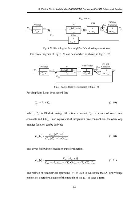
Fig. 3. 31. Block diagram for a simplified <strong>DC</strong>-link voltage control loop<br />
The block diagram <strong>of</strong> Fig. 3. 31 can be modified as shown in Fig. 3. 32.<br />
U dccc<br />
sT pfu<br />
1<br />
+ 1<br />
U dcc<br />
+<br />
−<br />
( sT + )<br />
K<br />
PU IU<br />
1<br />
U<br />
sT<br />
IU<br />
dcc<br />
sT UT<br />
1<br />
+ 1<br />
P VSR<br />
+<br />
P load<br />
−<br />
P cap<br />
1<br />
sCU dcc<br />
U dc<br />
U dcf<br />
For simplicity it can be assumed that:<br />
Fig. 3. 32. Modified block diagram <strong>of</strong> Fig. 3. 31<br />
T = T + T<br />
(3. 69)<br />
UT<br />
U<br />
IT<br />
Where,<br />
T<br />
U<br />
is <strong>DC</strong>-link voltage filter time constant, T UT<br />
is a sum <strong>of</strong> small time<br />
constants <strong>and</strong><br />
CU<br />
dcc<br />
is an equivalent <strong>of</strong> integration time constant. So, the open loop<br />
transfer function can be derived:<br />
G<br />
Uo<br />
() s<br />
IU<br />
PU<br />
( sTIU<br />
+ 1)<br />
( sTUT<br />
+ 1) sCU<br />
dcc<br />
K<br />
= (3. 70)<br />
sT<br />
This gives following closed loop transfer function:<br />
() s<br />
( sT + 1)<br />
K<br />
= (3. 71)<br />
T CT U<br />
PU IU<br />
GUz<br />
2<br />
3<br />
K<br />
PU<br />
+ sTIU<br />
K<br />
PU<br />
+ s TIUCU<br />
dcc<br />
+ s<br />
IU<br />
UT<br />
dcc<br />
The method <strong>of</strong> symmetrical optimum [134] is used to synthesize the <strong>DC</strong>-link voltage<br />
controller. Therefore, square <strong>of</strong> the module <strong>of</strong> Eq. (3.71) takes a form:<br />
66


![[TCP] Opis układu - Instytut Sterowania i Elektroniki Przemysłowej ...](https://img.yumpu.com/23535443/1/184x260/tcp-opis-ukladu-instytut-sterowania-i-elektroniki-przemyslowej-.jpg?quality=85)
