

Direct Power and Torque Control of AC/DC/AC Converter-Fed ...
Direct Power and Torque Control of AC/DC/AC Converter-Fed ...
Direct Power and Torque Control of AC/DC/AC Converter-Fed ...

Create successful ePaper yourself
Turn your PDF publications into a flip-book with our unique Google optimized e-Paper software.
Appendices<br />
3 ⎧2<br />
2 2<br />
2<br />
Im{} S = Q = Im⎨<br />
( U + + ) ( + + ) ⎬ ⎫<br />
A<br />
aU<br />
B<br />
a U<br />
C<br />
I<br />
A<br />
a I<br />
B<br />
aIC<br />
(A.3. 15)<br />
2 ⎩3<br />
3<br />
⎭<br />
Q<br />
1<br />
=<br />
3<br />
[ I ( U −U<br />
) + I ( U −U<br />
) + I ( U −U<br />
)]<br />
A<br />
B<br />
C<br />
B<br />
C<br />
A<br />
C<br />
A<br />
B<br />
(A.3.15a)<br />
1<br />
Q =<br />
A BC B CA<br />
+<br />
3<br />
( I U + I U I U )<br />
C<br />
AB<br />
(A.3.15b)<br />
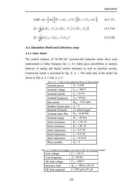
A.4. Simulation Model <strong>and</strong> Laboratory setup<br />
A.4.1. Saber Model<br />
The control schemes <strong>of</strong> <strong>AC</strong>/<strong>DC</strong>/<strong>AC</strong> converter-fed induction motor drive were<br />
implemented in Saber Synopsys Inc. v. 2.4. Saber gives possibilities to analysis<br />
behavior <strong>of</strong> analog <strong>and</strong> digital control structures as well as electrical circuits.<br />
Constructed model is presented in Fig. A. 4. 1 .The main data <strong>of</strong> the model are<br />
shown in Tab. A. 4. 1-Tab. A. 4. 3.<br />
Tab. A. 4. 1. Data <strong>of</strong> the Induction Motor in Saber Model<br />
Nominal power P<br />
N<br />
= 3 kW<br />
Nominal voltage U<br />
SN<br />
= 380 V<br />
Nominal current I<br />
SN<br />
= 6.9 A<br />
Nominal frequency f<br />
SN<br />
= 50 Hz<br />
Base speed<br />
Ω<br />
mN<br />
= 1415 rpm<br />
Number <strong>of</strong> pole pairs p<br />
b<br />
= 2<br />
Moment <strong>of</strong> inertia J = 0.0154 kgm 2<br />
Nominal stator flux Ψ<br />
SN<br />
= 0.98 Wb<br />
Nominal torque M<br />
N<br />
= 20 Nm<br />
Stator resistance R<br />
S<br />
= 1.84 Ω<br />
Rotor resistance R<br />
r<br />
= 1.84 Ω<br />
Stator inductance L<br />
S<br />
= 0.17 H<br />
Rotor inductance L<br />
r<br />
= 0.17 H<br />
Main inductance L<br />
M<br />
= 0.16 H<br />
Phase number m = 3<br />
S<br />
Tab. A. 4. 2.Data <strong>of</strong> the Supply Line <strong>and</strong> <strong>AC</strong>/<strong>DC</strong>/<strong>AC</strong> <strong>Converter</strong> Model<br />
Line voltage U<br />
L<br />
= 141 V<br />
Line frequency f<br />
L<br />
= 50 Hz<br />
<strong>DC</strong>-link voltage U<br />
<strong>DC</strong><br />
=560 V<br />
Resistive load R<br />
load<br />
= 100 or 150 Ω<br />
<strong>DC</strong>-link capacitor C =470 µFor 47 µF<br />
148


![[TCP] Opis układu - Instytut Sterowania i Elektroniki Przemysłowej ...](https://img.yumpu.com/23535443/1/184x260/tcp-opis-ukladu-instytut-sterowania-i-elektroniki-przemyslowej-.jpg?quality=85)
