

Direct Power and Torque Control of AC/DC/AC Converter-Fed ...
Direct Power and Torque Control of AC/DC/AC Converter-Fed ...
Direct Power and Torque Control of AC/DC/AC Converter-Fed ...

You also want an ePaper? Increase the reach of your titles
YUMPU automatically turns print PDFs into web optimized ePapers that Google loves.
3. Vector <strong>Control</strong> Methods <strong>of</strong> <strong>AC</strong>/<strong>DC</strong>/<strong>AC</strong> <strong>Converter</strong>-<strong>Fed</strong> IM Drives – A Review<br />
Further, for DPC needs it is assumed that R is negligible small <strong>and</strong> the switching<br />
devices in the VSR are ideal (i.e. they do not need dead-time <strong>and</strong> there is no forward<br />
voltage drops).<br />
From Fig. 3. 8 it can be seen that there are two power loops: for active P , <strong>and</strong><br />
reactive Q ones. Comm<strong>and</strong> active power P c<br />
is controlled by <strong>DC</strong>-link voltage loop,<br />
while the comm<strong>and</strong> reactive power<br />
Q c<br />
is given from the outside <strong>of</strong> the control<br />
scheme. Usually reactive power is set to be zero, to obtain a unity power factor<br />
operation. The <strong>DC</strong>-link voltage is maintaining to be constant by appropriate active<br />
power adjustment. Estimated values <strong>of</strong> the active power P <strong>and</strong> reactive power Q are<br />
compared with comm<strong>and</strong>ed values. The power errors e P<br />
<strong>and</strong> e Q<br />
are input signal to<br />
hysteresis comparators. At the output <strong>of</strong> the comparators are digitized signals S<br />
P<br />
<strong>and</strong><br />
S<br />
Q<br />
.<br />
In classical (voltage based) DPC from predefined switching table, based on<br />
signals<br />
S<br />
P<br />
, <strong>and</strong> S Q<br />
, <strong>and</strong> position <strong>of</strong> the line voltage<br />
γ<br />
UL<br />
, the appropriate voltage<br />
vector is selected. In virtual flux based VF-DPC instead <strong>of</strong> γ<br />
U<br />
the position <strong>of</strong> the<br />
L<br />
virtual flux<br />
γ<br />
Ψ<br />
are utilized in control algorithm. The outputs from the predefined<br />
L<br />
switching table (Tab. 3. 2) are the switching states S 1<br />
for the VSR. The powers<br />
hysteresis is defined in the same way for active <strong>and</strong> reactive power, therefore only<br />
for active power is given:<br />
Where,<br />
S<br />
P<br />
= 1 for e<br />
P<br />
> H<br />
P<br />
(3. 39)<br />
S<br />
P<br />
= 0 for eP<br />
< −H<br />
P<br />
(3. 40)<br />
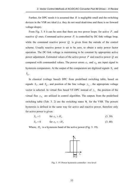
H<br />
P<br />
is a hysteresis b<strong>and</strong> <strong>of</strong> the active power (Fig. 3. 19).<br />
S P<br />
H P<br />
e P<br />
Fig. 3. 19. <strong>Power</strong> hysteresis controller - two level<br />
53


![[TCP] Opis układu - Instytut Sterowania i Elektroniki Przemysłowej ...](https://img.yumpu.com/23535443/1/184x260/tcp-opis-ukladu-instytut-sterowania-i-elektroniki-przemyslowej-.jpg?quality=85)
