On-Board® W Module Programming and Operation ... - PTB Sales
On-Board® W Module Programming and Operation ... - PTB Sales
On-Board® W Module Programming and Operation ... - PTB Sales
Create successful ePaper yourself
Turn your PDF publications into a flip-book with our unique Google optimized e-Paper software.
<strong>On</strong>-Board W <strong>Module</strong> <strong>Programming</strong> <strong>and</strong> <strong>Operation</strong><br />
CTI-CRYOGENICS<br />
HELIX TECHNOLOGY CORPORATION<br />
Table of Contents (continued)<br />
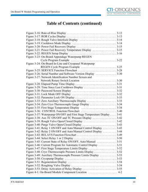
Figure 3-16: Rate-of-Rise Display . . . . . . . . . . . . . . . . . . . . . . . . . . . . . . . . . . 3-13<br />
Figure 3-17: ROR Cycles Display . . . . . . . . . . . . . . . . . . . . . . . . . . . . . . . . . . 3-13<br />
Figure 3-18: Rough Valve Interlock Display . . . . . . . . . . . . . . . . . . . . . . . . . 3-14<br />
Figure 3-19: Cooldown Mode Display . . . . . . . . . . . . . . . . . . . . . . . . . . . . . . 3-14<br />
Figure 3-20: Power Fail Recovery Display . . . . . . . . . . . . . . . . . . . . . . . . . . . 3-15<br />
Figure 3-21: Power Fail Recovery Temperature Display . . . . . . . . . . . . . . . . 3-15<br />
Figure 3-22: REGEN Setup Display . . . . . . . . . . . . . . . . . . . . . . . . . . . . . . . . 3-16<br />
Figure 3-23: <strong>On</strong>-Board Appendage Waterpump REGEN<br />
Cycle Program Example . . . . . . . . . . . . . . . . . . . . . . . . . . . . . . . 3-22<br />
Figure 3-24: <strong>On</strong>-Board In-Line <strong>and</strong> Cryopanel Waterpump<br />
REGEN Cycle Program Example . . . . . . . . . . . . . . . . . . . . . . . . 3-25<br />
Figure 3-25: SERVICE Function Flowchart . . . . . . . . . . . . . . . . . . . . . . . . . . 3-28<br />
Figure 3-26: Serial Number <strong>and</strong> Software Version Display . . . . . . . . . . . . . . 3-30<br />
Figure 3-27: Network Identification Number Screen <strong>and</strong><br />
Network Rotary Switch Location . . . . . . . . . . . . . . . . . . . . . . . . 3-30<br />
Figure 3-28: Elapsed Pump Time Display . . . . . . . . . . . . . . . . . . . . . . . . . . . . 3-31<br />
Figure 3-29: Time Since Last Cooldown Display . . . . . . . . . . . . . . . . . . . . . . 3-31<br />
Figure 3-30: Password Screen Display . . . . . . . . . . . . . . . . . . . . . . . . . . . . . . 3-32<br />
Figure 3-31: Lock Mode OFF Display . . . . . . . . . . . . . . . . . . . . . . . . . . . . . . 3-32<br />
Figure 3-32: Parameter Lock ON Display . . . . . . . . . . . . . . . . . . . . . . . . . . . . 3-33<br />
Figure 3-33: Zero Auxiliary Thermocouple Display . . . . . . . . . . . . . . . . . . . . 3-33<br />
Figure 3-34: Zero Cryo Thermocouple Gauge Display . . . . . . . . . . . . . . . . . . 3-34<br />
Figure 3-35: First Stage Temperature Display . . . . . . . . . . . . . . . . . . . . . . . . 3-34<br />
Figure 3-36: CONTROL Function Flowchart . . . . . . . . . . . . . . . . . . . . . . . . 3-40<br />
Figure 3-37: Waterpump ON/OFF <strong>and</strong> First Stage Temperature Display . . . . 3-41<br />
Figure 3-38: Aux TC ON/OFF <strong>and</strong> TC Pressure Display . . . . . . . . . . . . . . . . 3-42<br />
Figure 3-39: Rough Valve Open/Closed Display . . . . . . . . . . . . . . . . . . . . . . 3-42<br />
Figure 3-40: Purge Valve Open/Closed Display . . . . . . . . . . . . . . . . . . . . . . . 3-43<br />
Figure 3-41: Relay 1 ON/OFF <strong>and</strong> Auto/Manual Control Display . . . . . . . . . 3-43<br />
Figure 3-42: Relay 2 ON/OFF <strong>and</strong> Auto/Manual Control Display . . . . . . . . . 3-44<br />
Figure 3-43: RELAYS Function Flowchart . . . . . . . . . . . . . . . . . . . . . . . . . . . 3-49<br />
Figure 3-44: Select Relay 1 or 2 Display . . . . . . . . . . . . . . . . . . . . . . . . . . . . . 3-50<br />
Figure 3-45: Current State of Relay ON/OFF, Auto/Manual . . . . . . . . . . . . . 3-51<br />
Figure 3-46: Current Program for Automatic Control Display . . . . . . . . . . . . 3-51<br />
Figure 3-47: First Stage Temperature Limits Display . . . . . . . . . . . . . . . . . . . 3-52<br />
Figure 3-48: Cryo Thermocouple Pressure Limits Display . . . . . . . . . . . . . . . 3-52<br />
Figure 3-49: Auxiliary Thermocouple Pressure Limits Display . . . . . . . . . . . 3-53<br />
Figure 3-50: Cryopump Display . . . . . . . . . . . . . . . . . . . . . . . . . . . . . . . . . . . 3-53<br />
Figure 3-51: Regeneration Display . . . . . . . . . . . . . . . . . . . . . . . . . . . . . . . . . 3-54<br />
Figure 3-52: Roughing Valve Display . . . . . . . . . . . . . . . . . . . . . . . . . . . . . . . 3-54<br />
Figure 3-53: Delay Activation of Relay Display . . . . . . . . . . . . . . . . . . . . . . . 3-55<br />
Figure 4-1: <strong>On</strong>-Board <strong>Module</strong> Component Location . . . . . . . . . . . . . . . . . . . . 4-2<br />
P/N 8040365 10


