

1956 AMC Hudson Technical Service Manual Supplement
1956 AMC Hudson Technical Service Manual Supplement
1956 AMC Hudson Technical Service Manual Supplement

Create successful ePaper yourself
Turn your PDF publications into a flip-book with our unique Google optimized e-Paper software.
10 TECHNICAL SERVICE MANUAL<br />
the grooves since that will change their depth, nor from the<br />
lands since that will change the ring groove clearance and<br />
destroy ring to land seating.<br />
Piston Ring Installation<br />
Removal of glaze from the cylinder wall for quicker ring<br />
seating can be accomplished by various methods. Where an<br />
expanding type hone is used, do not use more than ten<br />
strokes (each stroke down and return) to recondition a cylinder<br />
wall.<br />
Successful ring installation depends upon cleanliness in<br />
handling parts and while honing the cylinder walls. The<br />
engine bearings and lubrication system must be protected<br />
from abrasives.<br />
Rigid type hones are not to be used to remove cylinder<br />
glaze as there is always a slight amount of taper in cylinder<br />
walls after the engine has been in service.<br />
Rings must be installed on the pistons with a ring installing<br />
tool to prevent distortion and ring breakage.<br />
For service ring replacement, follow the detailed instructions<br />
enclosed in the ring package.<br />
Prior to installing the piston and connecting rod assembly<br />
into engine, the piston ring gaps are to be arranged so<br />
that the gap for the oil ring is toward the inside of the block.<br />
The gaps on the compression rings are 120° apart. Do not<br />
locate a ring gap over the piston pin boss.<br />
CONNECTING RODS<br />
FIGURE 15—Piston Ring Location<br />
Checking Ring Groove Clearance<br />
Side clearance between land and piston ring should be:<br />
No. 1 ring groove .002"-.0035"<br />
No. 2 ring groove .002"-.004"<br />
No. 3 ring groove .001"-.0079"<br />
Piston ring width is:<br />
No. 1 chrome plated .0775"-.0780" wide<br />
No. 2 plain<br />
.0770"-.0780" wide<br />
No. 3 oil control ring is a three-piece type (two oil<br />
control wiper rails with a spacer of segmented<br />
steel between them).<br />
Roll the ring around the groove in which it is to operate.<br />
It must fit freely at all points.<br />
Checking Ring Gap Clearance<br />
Piston ring gap or joint clearance is measured in the bottom<br />
of the cylinder near the end of the ring travel area. To<br />
square the ring in the bore for checking joint clearance,<br />
place the ring in the bore. Then with an inverted piston,<br />
push the ring down near the lower end of the ring travel<br />
area.<br />
When other than standard ring sizes are used, rings<br />
should be individually fitted to their respective bores for a<br />
gap clearance of:<br />
No. 1 . 010"-.020"<br />
No. 2 . 010"-.0201'<br />
No. 3 . 015"-.055" (Gap of Rail)<br />
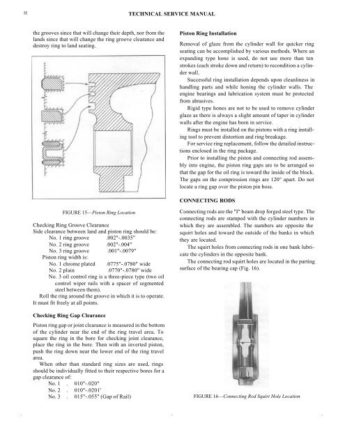
Connecting rods are the "I" beam drop forged steel type. The<br />
connecting rods are stamped with the cylinder numbers in<br />
which they are assembled. The numbers are opposite the<br />
squirt holes and toward the outside of the banks in which<br />
they are located.<br />
The squirt holes from connecting rods in one bank lubricate<br />
the cylinders in the opposite bank.<br />
The connecting rod squirt holes are located in the parting<br />
surface of the bearing cap (Fig. 16).<br />
FIGURE 16—Connecting Rod Squirt Hole Location


