

1956 AMC Hudson Technical Service Manual Supplement
1956 AMC Hudson Technical Service Manual Supplement
1956 AMC Hudson Technical Service Manual Supplement

Create successful ePaper yourself
Turn your PDF publications into a flip-book with our unique Google optimized e-Paper software.
68 TECHNICAL SERVICE MANUAL<br />
CAUTION: The feeler gauge must be flat against<br />
the thrust washer to obtain an accurate reading.<br />
Compare measurement found with feeler gauge with the<br />
chart in Figure 38 to determine the correct selective spacer<br />
washer to use. For example: if measurement is found to be<br />
.067", a number 6 selective spacer washer should be used<br />
when transmission is reassembled. Check the number on the<br />
original spacer (which was removed from the transmission).<br />
It should be the same as the number found on the chart. If<br />
not, a new spacer must be used for reassem bly. The identification<br />
number of the required spacer should be recorded<br />
so that it can be obtained for assembly.<br />
Remove Truarc snap ring, sun gear with bronze and steel<br />
thrust washers, internal gear with steel and bronze thrust<br />
washers, and .070" selective spacer washer.<br />
Remove gauge, sun gear with bronze and steel thrust<br />
washers, internal gear, with steel and bronze thrust washers,<br />
and .070" selective spacer washer.<br />
FRONT UNIT COUPLING, PRESSURE<br />
REGULATOR, AND COOLER<br />
ADAPTER REMOVAL<br />
Rotate transmission to horizontal position with oil pan "up."<br />
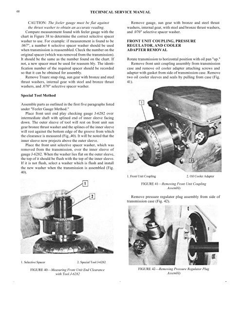
Remove front unit coupling assembly from transmission<br />
case and remove oil cooler adapter attaching screws and<br />
adapter with gasket from side of transmission case. Remove<br />
two oil cooler sleeves and seals by pulling from case (Fig.<br />
41).<br />
Special Tool Method<br />
Assemble parts as outlined in the first five paragraphs listed<br />
under "Feeler Gauge Method."<br />
Place front unit end play checking gauge J-6282 over<br />
intermediate shaft with splined end of inner sleeve facing<br />
down. The outer sleeve of tool will rest on front unit sun<br />
gear bronze thrust washer and the splines of the inner sleeve<br />
will rest against the bottom edge of the groove from which<br />
the clearance is measured (Fig.,40). It will be noted that the<br />
inner sleeve now projects above the outer sleeve.<br />
Place the front unit selective spacer washer, which was<br />
removed from the transmission, over the inner sleeve of<br />
gauge J-6282. When the washer lies flat on the outer sleeve,<br />
the top of it should be flush with the top of the inner sleeve.<br />
If it is not flush, select a washer which is flush and install<br />
the new washer when the transmission is assembled (Fig.<br />
40).<br />
1. Front Unit Coupling 2. Oil Cooler Adapter<br />
FIGURE 41—Removing Front Unit Coupling<br />
Assembly<br />
Remove pressure regulator plug assembly from side of<br />
transmission case (Fig. 42).<br />
1. Selective Spacer 2. Special Tool J-6282<br />
FIGURE 40—Measuring Front Unit End Clearance<br />
with Tool J-6282<br />
FIGURE 42—Removing Pressure Regulator Plug<br />
Assembly


