

1956 AMC Hudson Technical Service Manual Supplement
1956 AMC Hudson Technical Service Manual Supplement
1956 AMC Hudson Technical Service Manual Supplement

Create successful ePaper yourself
Turn your PDF publications into a flip-book with our unique Google optimized e-Paper software.
28 TECHNICAL SERVICE MANUAL<br />
it up for maximum output. When pressure becomes high, the<br />
pressure regulator valve is forced outward, directing oil<br />
pressure above the slide to push it down and decrease the<br />
output.<br />
When the slide is up, it delivers maximum output. When<br />
the slide is centered, output is zero.<br />
The torus check valve is held against the pump slide by<br />
spring pressure. When the slide moves down, oil will pass<br />
through the torus check valve and into the cooler passage<br />
from the cooler to the torus feed passage. If the cooler should<br />
become inoperative, oil from the torus check valve will<br />
unseat a ball check held in position by spring pressure and<br />
flow into the torus feed passage.<br />
REAR PUMP<br />
The rear pump is of the fixed displacement gear type and is<br />
driven by the output shaft; therefore, rear pump capacity will<br />
vary with car speed. At idle, the rear pump is not supplying<br />
oil to the transmission and all oil pressure will be supplied<br />
by the front pump.<br />
As the speed of the car increases, the oil from the rear<br />
pump will flow together with the front pump oil through a<br />
passage in the case. Much of the oil pressure requirements<br />
of the transmission will be taken over by the rear pump and<br />
the front pump will compensate by reducing its output.<br />
The basic requirements of a need for a rear pump was the<br />
necessity for oil pressure to supply the transmission in the<br />
event of a need for a push to start the vehicle.<br />
ACCUMULATOR<br />
To effect a smooth apply of the rear clutch, 2-3 oil being<br />
directed to the rear clutch apply piston is also directed to an<br />
accumulator. The accumulator contains a piston with heavy<br />
springs holding the piston in the down position which is<br />
opposing 2-3 oil directed to the other side of the piston. Oil<br />
from the 2-3 shift valve will move the accumulator piston<br />
against spring and oil pressure and also apply the rear clutch.<br />
Since the flow of oil to the accumulator and clutch apply<br />
piston is restricted, the accumulator is capable of collecting<br />
any oil that does flow through the restriction at the pressure<br />
valve which is required to move it. This maintains the<br />
pressure acting on the clutch piston, at a value below line<br />
pressure, until the accumulator is full. At that time, the<br />
pressure rises to line pressure. The engagement of the clutch<br />
must be completed before the accumulator is full to produce<br />
smooth shifts at the lower apply pressures.<br />
Clutch apply requirements will vary with throttle and load<br />
conditions. The accumulator is a factor in rear clutch engagement;<br />
its operation is varied accordingly by directing<br />
T.V. pressure to assist the spring in resisting 2-3 oil pressure.<br />
This T.V. pressure to the accumulator is regulated by a<br />
trimmer valve located in the accumulator body, held in the<br />
open position by spring and closed by T.V. pressure, thereby<br />
regulating T.V. pressure to the accumulator as the need<br />
requires.<br />
LOW SERVO<br />
The low servo located in the accumulator body is used to<br />
apply the low range band when the selector lever is moved<br />
to the "L" range position. Oil is directed from the manual<br />
valve to the servo to apply the low range band which holds<br />
the rear unit internal gear and prevents the vehicle from<br />
overrunning the rear sprag clutch when "L" range is being<br />
used for engine braking.<br />
HOW TO OPERATE THE FLASHAWAY HYDRA-MATIC<br />
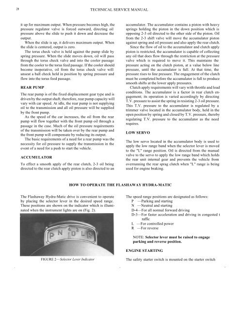
The Flashaway Hydra-Matic drive is convenient to operate<br />
by placing the selector lever in the desired speed range.<br />
These positions are shown on the indicator which is illuminated<br />
when the instrument lights are on (Fig. 2).<br />
The speed range positions are designated as follows:<br />
P —Parking and starting<br />
N —Neutral and starting<br />
D-4—For all normal forward driving<br />
D-3—For faster acceleration and driving in congested t<br />
raffic<br />
L —For controlled power<br />
R —For reverse<br />
NOTE: Selector lever must be raised to engage<br />
parking and reverse position.<br />
ENGINE STARTING<br />
FIGURE 2—Selector Lever Indicator<br />
The safety starter switch is mounted on the starter switch


