

1956 AMC Hudson Technical Service Manual Supplement
1956 AMC Hudson Technical Service Manual Supplement
1956 AMC Hudson Technical Service Manual Supplement

You also want an ePaper? Increase the reach of your titles
YUMPU automatically turns print PDFs into web optimized ePapers that Google loves.
20<br />
ELECTRICAL SECTION<br />
The twelve-volt electrical system is outlined in the <strong>1956</strong> Series<br />
<strong>Technical</strong> <strong>Service</strong> <strong>Manual</strong> <strong>Supplement</strong>.<br />
Delco-Remy electrical unit maintenance and adjustment procedures<br />
are outlined in the <strong>1956</strong> "Rambler" Series <strong>Technical</strong> <strong>Service</strong><br />
<strong>Manual</strong>. Specifications follow.<br />
DISTRIBUTOR<br />
The distributor, Delco-Remy Model 1110863, (Fig. 1) is a 12-volt,<br />
8-cylinder unit.<br />
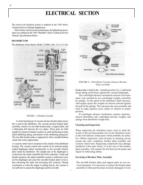
FIGURE 2—Distributor Vacuum Advance Breaker<br />
Plate Assembly<br />
FIGURE 1—Distributor Assembly<br />
A center bearing type of vacuum advance breaker plate assembly<br />
is used in this distributor. The vacuum advance breaker plate<br />
assembly consists of a movable breaker plate, a support plate, and<br />
a lubricating felt between the two plates. These parts are held<br />
together by means of retainer washers on a hub and bearing washer,<br />
spiral stabilizing spring, and retainer on the stabilizing spring post.<br />
The movable breaker plate is supported by three moulded buttons<br />
which ride on the support plate.<br />
A vacuum control unit is mounted on the outside of the distributor<br />
housing. The vacuum control unit consists of an enclosed springloaded<br />
diaphragm linked mechanically to the movable breaker<br />
plate inside the distributor. The airtight side of the diaphragm is<br />
connected to the intake manifold side of the carburetor. Under part<br />
throttle operation, the intake manifold vacuum is sufficient to actuate<br />
the diaphragm and cause the movable breaker plate to move,<br />
thus advancing the spark and increasing fuel economy. During<br />
acceleration or when the engine is pulling heavily, the vacuum is<br />
not sufficient to actuate the diaphragm and the movable<br />
breaker plate is held in the retarded position by a calibrated<br />
return spring which bears against the vacuum diaphragm.<br />
The centrifugal advance mechanism consists of an automatic<br />
cam actuated by two centrifugal weights controlled<br />
by springs. As the speed of the distributor shaft increases<br />
with engine speed, the weights are thrown outward against<br />
the pull of the springs. This advances the cam assembly and<br />
rotor to make ignition occur earlier in relation to piston<br />
position.<br />
If centrifugal advance mechanism requires attention,<br />
remove distributor cam, centrifugal advance weights, and<br />
springs from distributor weight base.<br />
Cleaning and Inspection<br />
When inspecting the distributor parts, keep in mind the<br />
results of the pre-disassembly test on the distributor tester<br />
as this will indicate certain parts which probably are defective.<br />
Before inspection, clean all parts in cleaning solvent<br />
except cap, rotor, condenser, breaker plate assembly and<br />
vacuum control unit. Degreasing compounds may damage<br />
insulation of the parts listed, or in the case of the breaker<br />
plate assembly, will saturate the felt between the plates and<br />
impair its lubricating ability.<br />
Servicing of Breaker Plate Assembly<br />
The movable breaker plate and support plate are not serviced<br />
separately. It is necessary to replace the breaker plate<br />
assembly if either part becomes seriously damaged or worn


