

1956 AMC Hudson Technical Service Manual Supplement
1956 AMC Hudson Technical Service Manual Supplement
1956 AMC Hudson Technical Service Manual Supplement

Create successful ePaper yourself
Turn your PDF publications into a flip-book with our unique Google optimized e-Paper software.
14 TECHNICAL SERVICE MANUAL<br />
Figure 23 illustrates a vibration damper puller which<br />
may be fabricated locally.<br />
FIGURE 23—Suggested Damper Puller<br />
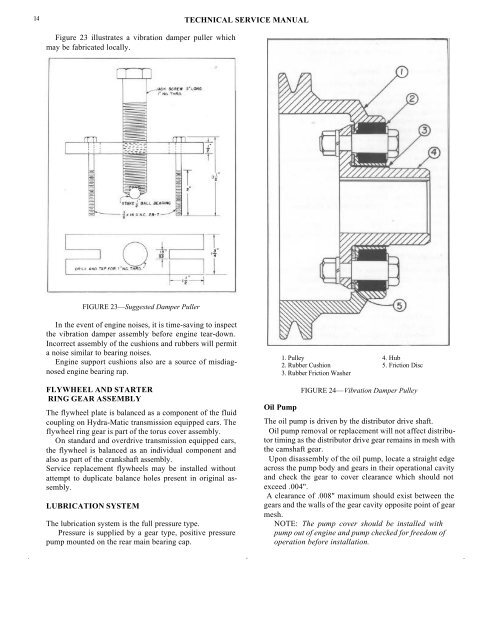
In the event of engine noises, it is time-saving to inspect<br />
the vibration damper assembly before engine tear-down.<br />
Incorrect assembly of the cushions and rubbers will permit<br />
a noise similar to bearing noises.<br />
Engine support cushions also are a source of misdiagnosed<br />
engine bearing rap.<br />
FLYWHEEL AND STARTER<br />
RING GEAR ASSEMBLY<br />
The flywheel plate is balanced as a component of the fluid<br />
coupling on Hydra-Matic transmission equipped cars. The<br />
flywheel ring gear is part of the torus cover assembly.<br />
On standard and overdrive transmission equipped cars,<br />
the flywheel is balanced as an individual component and<br />
also as part of the crankshaft assembly.<br />
<strong>Service</strong> replacement flywheels may be installed without<br />
attempt to duplicate balance holes present in original assembly.<br />
LUBRICATION SYSTEM<br />
The lubrication system is the full pressure type.<br />
Pressure is supplied by a gear type, positive pressure<br />
pump mounted on the rear main bearing cap.<br />
1. Pulley 4. Hub<br />
2. Rubber Cushion 5. Friction Disc<br />
3. Rubber Friction Washer<br />
Oil Pump<br />
FIGURE 24—Vibration Damper Pulley<br />
The oil pump is driven by the distributor drive shaft.<br />
Oil pump removal or replacement will not affect distributor<br />
timing as the distributor drive gear remains in mesh with<br />
the camshaft gear.<br />
Upon disassembly of the oil pump, locate a straight edge<br />
across the pump body and gears in their operational cavity<br />
and check the gear to cover clearance which should not<br />
exceed .004".<br />
A clearance of .008" maximum should exist between the<br />
gears and the walls of the gear cavity opposite point of gear<br />
mesh.<br />
NOTE: The pump cover should be installed with<br />
pump out of engine and pump checked for freedom of<br />
operation before installation.


