

1956 AMC Hudson Technical Service Manual Supplement
1956 AMC Hudson Technical Service Manual Supplement
1956 AMC Hudson Technical Service Manual Supplement

Create successful ePaper yourself
Turn your PDF publications into a flip-book with our unique Google optimized e-Paper software.
ENGINE V-8 5<br />
Valve Refacing<br />
The intake valves are faced to a 29° angle and the exhaust<br />
valves to a 44° angle. Valves may be refaced until remaining<br />
margin is down to 1/32"; then the valve must be replaced.<br />
The valve stem tip when worn can be resurfaced and<br />
rechamfered. However, never remove more than .010".<br />
Valve Seat Refacing<br />
Valve Springs<br />
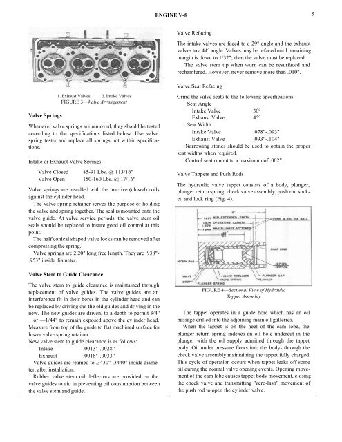
1. Exhaust Valves 2. Intake Valves<br />
FIGURE 3—Valve Arrangement<br />
Whenever valve springs are removed, they should be tested<br />
according to the specifications listed below. Use valve<br />
spring tester and replace all springs not within specifications.<br />
Intake or Exhaust Valve Springs:<br />
Valve Closed 85-91 Lbs. @ 113/16"<br />
Valve Open 150-160 Lbs. @ 17/16"<br />
Valve springs are installed with the inactive (closed) coils<br />
against the cylinder head.<br />
The valve spring retainer serves the purpose of holding<br />
the valve and spring together. The seal is mounted onto the<br />
valve guide. At valve service periods, the valve stem oil<br />
seals should be replaced to insure good oil control at this<br />
point.<br />
The half conical shaped valve locks can be removed after<br />
compressing the spring.<br />
Valve springs are 2.20" long free length. They are .938"-<br />
.953" inside diameter.<br />
Grind the valve seats to the following specifications:<br />
Seat Angle<br />
Intake Valve 30°<br />
Exhaust Valve 45°<br />
Seat Width<br />
Intake Valve .078"-.093"<br />
Exhaust Valve .093"-.104"<br />
Narrowing stones should be used to obtain the proper<br />
seat widths when required.<br />
Control seat runout to a maximum of .002".<br />
Valve Tappets and Push Rods<br />
The hydraulic valve tappet consists of a body, plunger,<br />
plunger return spring, check valve assembly, push rod socket,<br />
and lock ring (Fig. 4).<br />
Valve Stem to Guide Clearance<br />
The valve stem to guide clearance is maintained through<br />
replacement of valve guides. The valve guides are an<br />
interference fit in their bores in the cylinder head and can<br />
be replaced by driving out the old guides and driving in the<br />
new. The new guides are driven, to a depth to permit 3/4"<br />
+ or —1/44" to remain exposed above the cylinder head.<br />
Measure from top of the guide to flat machined surface for<br />
lower valve spring retainer.<br />
New valve stem to guide clearance is as follows:<br />
Intake .0013"-.0028"<br />
Exhaust .0018"-.0033"<br />
Valve guides are reamed to .3430"-.3440" inside diameter,<br />
after installation.<br />
Rubber valve stem oil deflectors are provided on the<br />
valve guides to aid in preventing oil consumption between<br />
the valve stem and guide.<br />
FIGURE 4—Sectional View of Hydraulic<br />
Tappet Assembly<br />
The tappet operates in a guide bore which has an oil<br />
passage drilled into the adjoining main oil galleries.<br />
When the tappet is on the heel of the cam lobe, the<br />
plunger return spring indexes an oil hole undercut in the<br />
plunger with the oil supply admitted through the tappet<br />
body. Oil under pressure flows into the body- through the<br />
check valve assembly maintaining the tappet fully charged.<br />
This cycle of operation occurs when tappet leaks off some<br />
oil during the normal valve opening events. Opening movement<br />
of the cam lobe causes tappet body movement, closing<br />
the check valve and transmitting "zero-lash" movement of<br />
the push rod to open the cylinder valve.


