QUICK & CRASH - The International Arcade Museum
QUICK & CRASH - The International Arcade Museum
QUICK & CRASH - The International Arcade Museum

Create successful ePaper yourself
Turn your PDF publications into a flip-book with our unique Google optimized e-Paper software.
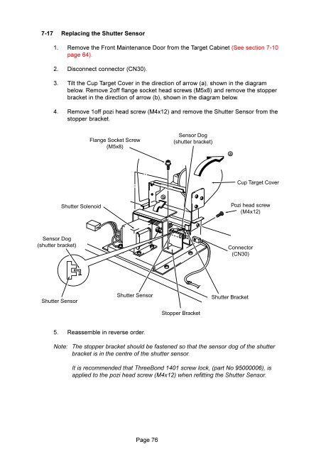
7-17 Replacing the Shutter Sensor<br />
1. Remove the Front Maintenance Door from the Target Cabinet (See section 7-10<br />
page 64).<br />
2. Disconnect connector (CN30).<br />
3. Tilt the Cup Target Cover in the direction of arrow (a), shown in the diagram<br />
below. Remove 2off flange socket head screws (M5x8) and remove the stopper<br />
bracket in the direction of arrow (b), shown in the diagram below.<br />
4. Remove 1off pozi head screw (M4x12) and remove the Shutter Sensor from the<br />
stopper bracket.<br />
Flange Socket Screw<br />
(M5x8)<br />
Sensor Dog<br />
(shutter bracket)<br />
a<br />
Cup Target Cover<br />
Shutter Solenoid<br />
b<br />
Pozi head screw<br />
(M4x12)<br />
Sensor Dog<br />
(shutter bracket)<br />
Connector<br />
(CN30)<br />
Shutter Sensor<br />
Shutter Sensor<br />
Shutter Bracket<br />
Stopper Bracket<br />
5. Reassemble in reverse order.<br />
Note: <strong>The</strong> stopper bracket should be fastened so that the sensor dog of the shutter<br />
bracket is in the centre of the shutter sensor.<br />
It is recommended that ThreeBond 1401 screw lock, (part No 95000006), is<br />
applied to the pozi head screw (M4x12) when refitting the Shutter Sensor.<br />
Page 76