Inogen One G3 Technical Manual
Inogen One G3 Technical Manual
Inogen One G3 Technical Manual

Create successful ePaper yourself
Turn your PDF publications into a flip-book with our unique Google optimized e-Paper software.
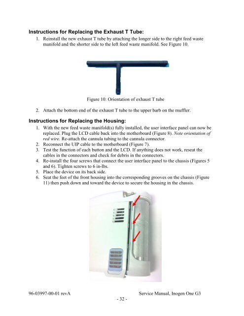
Instructions for Replacing the Exhaust T Tube:<br />
1. Reinstall the new exhaust T tube by attaching the longer side to the right feed waste<br />
manifold and the shorter side to the left feed waste manifold. See Figure 10.<br />
Figure 10: Orientation of exhaust T tube<br />
2. Attach the bottom end of the exhaust T tube to the upper barb on the muffler.<br />
Instructions for Replacing the Housing:<br />
1. With the new feed waste manifold(s) fully installed, the user interface panel can now be<br />
replaced. Plug the LCD cable back into the motherboard (Figure 8). Note orientation of<br />
red wire. Re-attach the cannula tubing to the cannula connector.<br />
2. Reconnect the UIP cable to the motherboard (Figure 7).<br />
3. Test the function of each button and the LCD. If anything does not work, reseat the<br />
cables in the connectors and check for debris in the connectors.<br />
4. Re-install the four screws that connect the user interface panel to the chassis (Figures 5<br />
and 6). Tighten screws to 6 in-lbs.<br />
5. Place the device on its back side.<br />
6. Seat the feet of the front housing into the corresponding grooves on the chassis (Figure<br />
11) then push down and toward the device to secure the housing in the chassis.<br />
96-03997-00-01 revA Service <strong>Manual</strong>, <strong>Inogen</strong> <strong>One</strong> <strong>G3</strong><br />
- 32 -