Inogen One G3 Technical Manual
Inogen One G3 Technical Manual
Inogen One G3 Technical Manual

You also want an ePaper? Increase the reach of your titles
YUMPU automatically turns print PDFs into web optimized ePapers that Google loves.
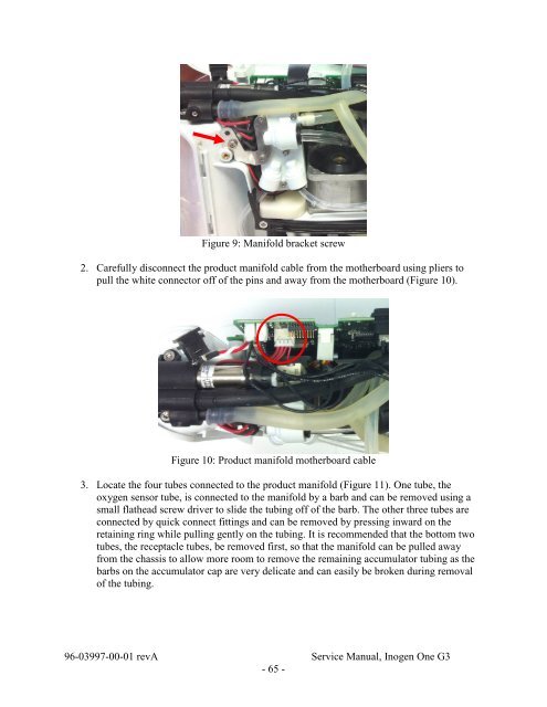
Figure 9: Manifold bracket screw<br />
2. Carefully disconnect the product manifold cable from the motherboard using pliers to<br />
pull the white connector off of the pins and away from the motherboard (Figure 10).<br />
Figure 10: Product manifold motherboard cable<br />
3. Locate the four tubes connected to the product manifold (Figure 11). <strong>One</strong> tube, the<br />
oxygen sensor tube, is connected to the manifold by a barb and can be removed using a<br />
small flathead screw driver to slide the tubing off of the barb. The other three tubes are<br />
connected by quick connect fittings and can be removed by pressing inward on the<br />
retaining ring while pulling gently on the tubing. It is recommended that the bottom two<br />
tubes, the receptacle tubes, be removed first, so that the manifold can be pulled away<br />
from the chassis to allow more room to remove the remaining accumulator tubing as the<br />
barbs on the accumulator cap are very delicate and can easily be broken during removal<br />
of the tubing.<br />
96-03997-00-01 revA Service <strong>Manual</strong>, <strong>Inogen</strong> <strong>One</strong> <strong>G3</strong><br />
- 65 -