Inogen One G3 Technical Manual
Inogen One G3 Technical Manual
Inogen One G3 Technical Manual

You also want an ePaper? Increase the reach of your titles
YUMPU automatically turns print PDFs into web optimized ePapers that Google loves.
Instructions for Replacing the Housing:<br />
1. To re-install the user interface panel, plug the LCD cable back into the motherboard<br />
(Figure 8). Note orientation of red wire. Re-attach the cannula tubing to the cannula<br />
connector.<br />
2. Reconnect the UIP cable to the motherboard (Figure 7).<br />
3. Test the function of each button and the LCD. If anything does not work, reseat the<br />
cables in the connectors and check for debris in the connectors.<br />
4. Re-install the four screws that connect the user interface panel to the chassis (Figures 5<br />
and 6). Tighten screws to 6 in-lbs.<br />
5. Place the device on its back side.<br />
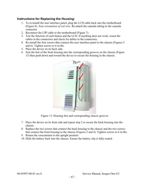
6. Seat the feet of the front housing into the corresponding grooves on the chassis (Figure<br />
13) then push down and toward the device to secure the housing in the chassis.<br />
Figure 13: Housing feet and corresponding chassis grooves<br />
7. Place the device on its front side and repeat step 2 to secure the back housing into the<br />
chassis.<br />
8. Replace the two screws that connect the back housing to the chassis and the two screws<br />
that connect the front housing to the chassis (Figures 2 and 4). Tighten screws to 6 in-lbs.<br />
9. Return the concentrator to the upright position<br />
10. Slide the battery back into the chassis. Ensure the battery clip is fully seated.<br />
96-03997-00-01 revA Service <strong>Manual</strong>, <strong>Inogen</strong> <strong>One</strong> <strong>G3</strong><br />
- 67 -