

Editorial & Advisory Board - Acta Technica Corviniensis
Editorial & Advisory Board - Acta Technica Corviniensis
Editorial & Advisory Board - Acta Technica Corviniensis

You also want an ePaper? Increase the reach of your titles
YUMPU automatically turns print PDFs into web optimized ePapers that Google loves.
ACTA TECHNICA CORVINIENSIS – Bulletin of Engineering<br />
where Ft (f3=0) is drawing force generated by a rotating<br />
roller, Ft (f3>0) is drawing force generated by a fixed<br />
roller, f 3 is friction coefficient on the die drawing<br />
edge.<br />
FEM SIMULATION OF STRIP DRAWN TEST<br />
Strip drawing simulation was realized using software<br />
Pam‐Stamp2G. Model of experimental device was<br />
created in 3D CAD/CAM software Pro/Engineer and its<br />
components were exported in neutral format igs. The<br />
die geometry was created according to real testing<br />
device: drawing die radius 10 mm, flat die part<br />
dimensions 30 in length and 50 mm in width (area of<br />
blankholder). Meshing of die components and strip<br />
were realized in meshing module of Pam‐Stamp 2G<br />
during models import. Meshed die components are<br />
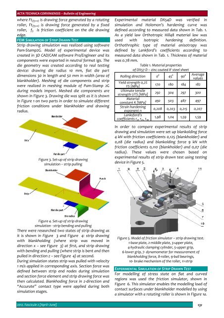
shown in Figure 3. Drawing die was split as it is shown<br />
in Figure 1 on two parts in order to simulate different<br />
friction conditions under blankholder and drawing<br />
radius.<br />
Figure 3. Set‐up of strip drawing<br />
simulation – strip pulling<br />
Experimental material DX54D was verified in<br />
simulation and Holomon’s hardening curve was<br />
defined according to measured data shown in Tab. 1.<br />
As a yield law Orthotropic Hill48 material law was<br />
used with Isotropic hardening definition.<br />
Orthothrophic type of material anisotropy was<br />
defined by Lankford’s coefficients according to<br />
measured data shown in Tab. 1. Thickness of material<br />
was 0.78 mm.<br />
Table 1. Material properties<br />
of DX57 D – zinc coated IF steel sheet<br />
Rolling direction 0° 45° 90°<br />
Average<br />
values<br />
Yield strength 0,2%<br />
YS [MPa]<br />
170 180 184 182<br />
Ultimate tensile<br />
strength UTS [MPa]<br />
292 304 297 300<br />
Material<br />
constant K [MPa]<br />
492 503 487 497<br />
Strain hardening<br />
exponent n<br />
0,208 0,203 0,215 0,207<br />
Lanksford’s<br />
coefficients r 0 , r 45, r 90<br />
1,98 1,04 1,59 1,59<br />
In order to compare experimental results of strip<br />
drawing and simulation were set up blankolding force<br />
4 kN with friction coefficients 0,125 (blankholder) and<br />
0,08 (die radius) and blankolding force 9 kN with<br />
friction coefficients 0,110 (blankholder) and 0,07 (die<br />
radius). These values were chosen based on<br />
experimental results of strip drawn test using testing<br />
device in Figure 5.<br />
Figure 4. Set‐up of strip drawing<br />
simulation ‐ strip bending and pulling<br />
There were researched two states of strip drawing as<br />
it is shown in Figure 3 and Figure 4: strip drawing<br />
with blankholding (where strip was moved in<br />
direction x – see Figure 3) at first, and strip drawing<br />
with bending and pulling (where strip is bent and then<br />
pulled in direction z – see Figure 4) at second.<br />
During simulation states strip was pulled with velocity<br />
1 m/s applied in corresponding axis. Section force was<br />
defined between strip end nodes during simulation<br />
and section force element and strip drawing force was<br />
then calculated. Blankhoding force in z‐direction and<br />
“Accurate” contact type were applied during both<br />
simulation stages.<br />
Figure 5. Model of friction simulator – strip drawing test.<br />
1‐base plate, 2‐middle plate, 3‐upper plate,<br />
4‐hydraulic clamping cylinder, 5‐upper grip,<br />
6‐lower grip, 7‐ dynamometer for measurement of<br />
blankholding force, 8‐roller, 9‐ball bearings,<br />
10‐ brake mechanism of the roller, 11‐strip<br />
EXPERIMENTAL SIMULATION OF STRIP DRAWN TEST<br />
For modelling of stress state on flat and curved<br />
regions was used the friction simulator, shown in<br />
Figure 6. This simulator enables the modelling load of<br />
contact surfaces under blankholder modelled by using<br />
a simulator with a rotating roller is shown in Figure 1a.<br />
2012. Fascicule 2 [April–June] 131


