

Editorial & Advisory Board - Acta Technica Corviniensis
Editorial & Advisory Board - Acta Technica Corviniensis
Editorial & Advisory Board - Acta Technica Corviniensis

Create successful ePaper yourself
Turn your PDF publications into a flip-book with our unique Google optimized e-Paper software.
Load of contact areas on the die drawing edge with a<br />
fixed roller is shown in Figure 1a,b.<br />
Drawing conditions were as follows: blankholding<br />
forces FN = 4.0, 9.0 kN, strip drawing speed v = 10<br />
mm/s, roughness of the upper and lower grips Ra = 0.4<br />
µm, roughness of roller Ra = 0.4 µm. The surface of<br />
steel strip was lubricated with lubricant Anticorit<br />
Prelube 3802‐39 S with a kinematic viscosity of 60<br />
mm2/s at 40 °C in the amount of 2 g/m2.<br />
Table 2 and Table 3 shows adjusted values of<br />
blankholding forces F N and friction coefficients for<br />
simulation, measured drawing forces F f1N , F p(f3=0) and<br />
F p(f3>0) . For evaluation of friction coefficient in the area<br />
under blankholder were applied analytical Eq.(1) and<br />
Eq. (13). The Eq.(17) for calculation of friction<br />
coefficient f 3 on drawing edge of stamping die was<br />
used.<br />
Table 2. Calculated friction coefficients<br />
– strip drawing without bending (Figure 3)<br />
Material<br />
DX 54 D<br />
Blankholding<br />
force<br />
F N [N]<br />
Drawing<br />
forces [N]<br />
State 1<br />
F f1N<br />
[N]<br />
Friction<br />
coefficients<br />
f 1,2<br />
according<br />
to relation (1)<br />
f 1,2<br />
according<br />
to relation<br />
(13)<br />
FEM simulation, 4000 999 0,125 ‐<br />
f initial = 0,125 9000 2254 0,125 0,125<br />
FEM simulation, 4000 878 0,11 ‐<br />
f initial = 0,11 9000 1981 0,11 0,11<br />
Experiment<br />
4000 998 0,125<br />
9000 1986 0,11 0.099<br />
FEM simulation 4000 100,1 100 ‐<br />
and Experiment<br />
conformity [%]<br />
9000 99,7 100 90‐100<br />
Note: State 1 – strip pulling within flat surfaces of<br />
blankholder and die<br />
Material<br />
DX 54 D<br />
Table 3. Calculated friction coefficients<br />
– strip drawing with bending (Figure 4)<br />
Blankholding<br />
Force FN [N]<br />
Drawing<br />
forces [N]<br />
State 2<br />
Fp (f3=0) [N]<br />
State 3<br />
Fp (f3>0) [N]<br />
Friction coefficients<br />
f 1,2 acc.<br />
to rel. (13)<br />
f 1,2 acc.<br />
to rel. (1)<br />
FEM 4000 1362 1546 0,17 0,08<br />
simulation,<br />
f initial = 0,125 9000 2631 ‐ 0,127 0,146<br />
FEM 4000 1246 ‐ 0,156<br />
simulation,<br />
f initial = 0,11 9000 2365 2619 0,117 0,131 0,065<br />
Experiment<br />
4000 1108 1258 0,125 0,08<br />
9000 2361 2646 0,099 0,11 0,07<br />
FEM<br />
4000 120 123 ‐ 136 100<br />
simulation<br />
and xperiment<br />
100 ‐<br />
conformity [%] 9000 100 99<br />
119 93<br />
106<br />
Note: State 2 – strip pulling and bending along rotating<br />
cylinder; State 3 – strip pulling and bending along fixed<br />
cylinder<br />
F 3 acc. to rel.(17)<br />
ACTA TECHNICA CORVINIENSIS – Bulletin of Engineering<br />
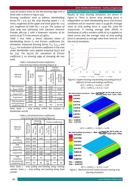
REACHED RESULTS AND DISCUSSION<br />
Results of strip drawing simulation are shown in<br />
Figure 6. There is shown strip bending force is<br />
independent on both blankholding force and friction<br />
conditions and its maximal value is 0,439 kN. Average<br />
value of strip pulling force is 1,546 kN; 2,619 kN<br />
respectively. A moving average filter (MVA) in<br />
PamStamp 2G with a window width of 25 is applied on<br />
these curves and the average value of strip pulling<br />
force is calculated as average value from time 60 s till<br />
the end of simulation.<br />
Figure 6. Graphs showing strip bending and pulling force at<br />
different friction and holding conditions.<br />
a) F N = 4 kN; f 1,2 = 0,125; f 3 = 0,08<br />
b) F N = 9 kN; f 1,2 = 0,11; f 3 = 0,07<br />
a) F N = 4 kN; f 1,2 = 0,125; f 3 = 0,08;<br />
b) F N = 9 kN; f 1,2 = 0,11; f 3 = 0,07<br />
Figure 7. Maximal normal contact pressure during strip<br />
drawing simulation<br />
132<br />
2012. Fascicule 2 [April–June]


