

Editorial & Advisory Board - Acta Technica Corviniensis
Editorial & Advisory Board - Acta Technica Corviniensis
Editorial & Advisory Board - Acta Technica Corviniensis

Create successful ePaper yourself
Turn your PDF publications into a flip-book with our unique Google optimized e-Paper software.
Significant increase in the concentration of carbon at<br />
the beginning of the combined zone can be seen from<br />
Figure 3, where it reaches the level of 0,52% and slightly<br />
decreases at the end of the carbonitrided zone, going to<br />
about 0,48 %. The distribution of the nitrogen in the<br />
carbonitrided zone changes gradually and its<br />
concentration at the end of the combined zone reaches<br />
the level of 7%, while at the beginning of the combined<br />
zone it is about 12,2 %. Under this mode of treatment the<br />
highest level of nitrogen concentration 12.2 % is achieved<br />
in the combined zone and the most gradual change of<br />
the content of nitrogen and carbon in the formed layer<br />
occur in comparison to all the other modes of ion<br />
carbonitriding of 25CrMnSiNiMo steel.<br />
ARMCO‐IRON<br />
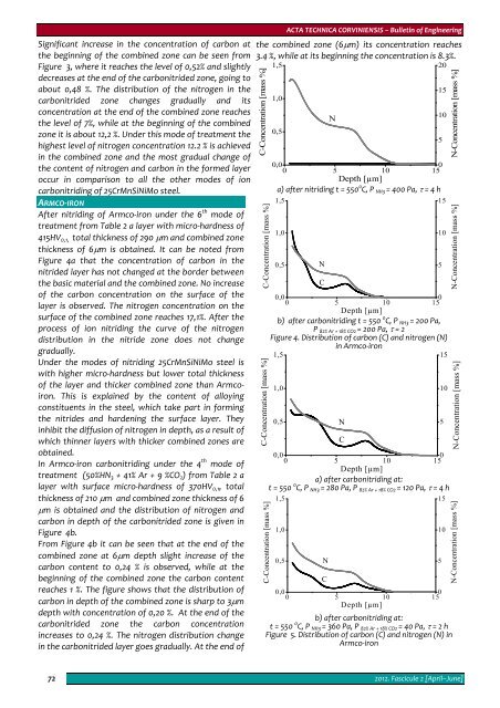
After nitriding of Armco‐iron under the 6 th mode of<br />
treatment from Table 2 a layer with micro‐hardness of<br />
415HV 0,1, total thickness of 290 μm and combined zone<br />
thickness of 6μm is obtained. It can be noted from<br />
Figure 4a that the concentration of carbon in the<br />
nitrided layer has not changed at the border between<br />
the basic material and the combined zone. No increase<br />
of the carbon concentration on the surface of the<br />
layer is observed. The nitrogen concentration on the<br />
surface of the combined zone reaches 17,1%. After the<br />
process of ion nitriding the curve of the nitrogen<br />
distribution in the nitride zone does not change<br />
gradually.<br />
Under the modes of nitriding 25CrMnSiNiMo steel is<br />
with higher micro‐hardness but lower total thickness<br />
of the layer and thicker combined zone than Armcoiron.<br />
This is explained by the content of alloying<br />
constituents in the steel, which take part in forming<br />
the nitrides and hardening the surface layer. They<br />
inhibit the diffusion of nitrogen in depth, as a result of<br />
which thinner layers with thicker combined zones are<br />
obtained.<br />
In Armco‐iron carbonitriding under the 4 th mode of<br />
treatment (50%HN 3 + 41% Ar + 9 %CO 2 ) from Table 2 a<br />
layer with surface micro‐hardness of 370HV 0,1 , total<br />
thickness of 210 μm and combined zone thickness of 6<br />
μm is obtained and the distribution of nitrogen and<br />
carbon in depth of the carbonitrided zone is given in<br />
Figure 4b.<br />
From Figure 4b it can be seen that at the end of the<br />
combined zone at 6μm depth slight increase of the<br />
carbon content to 0,24 % is observed, while at the<br />
beginning of the combined zone the carbon content<br />
reaches 1 %. The figure shows that the distribution of<br />
carbon in depth of the combined zone is sharp to 3μm<br />
depth with concentration of 0,20 %. At the end of the<br />
carbonitrided zone the carbon concentration<br />
increases to 0,24 %. The nitrogen distribution change<br />
in the carbonitrided layer goes gradually. At the end of<br />
ACTA TECHNICA CORVINIENSIS – Bulletin of Engineering<br />
the combined zone (6μm) its concentration reaches<br />
3.4 %, while at its beginning the concentration is 8.3%.<br />
C-Concentration [mass %]<br />
C-Concentration [mass %]<br />
C-Concentration [mass %]<br />
C-Concentration [mass %]<br />
1,5<br />
1,0<br />
0,5<br />
N<br />
0,0<br />
0 5 10<br />
0<br />
15<br />
Depth [µm]<br />
а) after nitriding t = 550 0 C, P NH3 = 400 Pa, τ = 4 h<br />
1,5<br />
1,0<br />
0,5<br />
N<br />
C<br />
0,0<br />
0<br />
0 5 10 15<br />
Depth [µm]<br />
b) after carbonitriding t = 550 0 C, P NH3 = 200 Pa,<br />
P 82% Ar + 18% CO2 = 200 Pa, τ = 2<br />
Figure 4. Distribution of carbon (С) and nitrogen (N)<br />
in Armco‐iron<br />
1,5<br />
15<br />
1,0<br />
0,5<br />
0,0<br />
0<br />
0 5 10 15<br />
Depth [µm]<br />
a) after carbonitriding at:<br />
t = 550 0 C, P NH3 = 280 Pa, P 82% Ar + 18% CO2 = 120 Pa, τ = 4 h<br />
1,5<br />
1,0<br />
0,5<br />
N<br />
C<br />
N<br />
C<br />
0,0<br />
0<br />
0 5 10 15<br />
Depth [µm]<br />
b) after carbonitriding at:<br />
t = 550 0 C, P NH3 = 360 Pa, P 82% Ar + 18% CO2 = 40 Pa, τ = 2 h<br />
Figure 5. Distribution of carbon (С) and nitrogen (N) in<br />
Armco‐iron<br />
20<br />
15<br />
10<br />
5<br />
15<br />
10<br />
5<br />
10<br />
5<br />
15<br />
10<br />
5<br />
N-Concentration [mass %]<br />
N-Concentration [mass %]<br />
N-Concentration [mass %]<br />
N-Concentration [mass %]<br />
72<br />
2012. Fascicule 2 [April–June]


