

Editorial & Advisory Board - Acta Technica Corviniensis
Editorial & Advisory Board - Acta Technica Corviniensis
Editorial & Advisory Board - Acta Technica Corviniensis

You also want an ePaper? Increase the reach of your titles
YUMPU automatically turns print PDFs into web optimized ePapers that Google loves.
METHODOLOGY OF INVESTIGATION HEAT TREATMENT<br />
The following materials have been chosen for the<br />
investigation: Armco‐iron and construction steel alloy ‐<br />
25CrMnSiNiMo. The chemical composition of the<br />
above materials has been tested by means of<br />
equipment for automatic analysis “Spectrotest” and<br />
given in Table 1.<br />
Table 1. Chemical composition of the investigated materials<br />
Materials<br />
Chemical elements, weight percentages<br />
С Si Mn Cr Ni<br />
Armco‐iron 0.02 0.01 0.07 0.02 0.03<br />
25CrMnSiNiMo 0.24 1.45 1.28 0.87 1.36<br />
Materials<br />
Chemical elements, weight percentages<br />
S P Мо V<br />
Armco‐iron 0.002 0.002 0.02 ‐<br />
25CrMnSiNiMo 0.002 0.002 0.12 ‐<br />
Samples, sizing 15 х 15 х 10 mm, have been made from the<br />
materials; 25CrMnSiNiMo steel has been thermally treated<br />
to hardness 35HRC, and the hardness of the Armco‐iron<br />
is 75HB. Treated this way, the samples have been then<br />
grinded to surface roughness R a = 0.63 µm. Afterwards<br />
they have been ion nitrided and carbonitrided in an<br />
installation for nitriding “Ion‐20” under the modes,<br />
given in Table 2. Ammonia (NH 3 ) and corgon (82 % Ar и<br />
18% CO 2 ) in different percentages have been used as<br />
saturating gases. The temperature of treatment for<br />
both processes – nitriding and carbonitriding – is<br />
550 о С.<br />
Table 2. Modes and results from the ion carbonitriding and<br />
the nitriding of the samples from 25CrMnSiNiMo–steel and<br />
Armco‐iron<br />
P 25CrMnSiNiMo<br />
№ τ<br />
1 P 2 Р<br />
NH<br />
mode [h] 3 corgon total<br />
δ<br />
HV tot δ с.z<br />
[Pa] [Ра] [Ра] 0,1<br />
[µm] [µm]<br />
1 2 360 40 400 940 160 5<br />
2 6 360 40 400 860 290 8<br />
3 6 200 200 400 920 240 8<br />
4 2 200 200 400 890 150 5<br />
5 4 280 120 400 930 210 9<br />
6 4 400 ‐ 400 1072 250 10<br />
№<br />
mode<br />
70<br />
τ<br />
[h]<br />
P 1<br />
NH 3<br />
[Pa]<br />
P 2<br />
corg<br />
on<br />
[Ра]<br />
Р<br />
total<br />
[Ра]<br />
HV0,1<br />
Armco‐iron<br />
δ tot<br />
[µm]<br />
δ с.z<br />
[µm]<br />
U<br />
[V]<br />
1 2 360 40 400 430 260 6 470<br />
2 6 360 40 400 420 340 7.5 470<br />
3 6 200 200 400 440 330 7 415<br />
4 2 200 200 400 370 210 6 415<br />
5 4 280 120 400 480 280 7 435<br />
6 4 400 ‐ 400 415 290 6 530<br />
GLOW DISCHARGE OPTICAL EMISSION SPECTROSCOPY<br />
The process of defining the distribution of nitrogen<br />
and carbon in the nitrided and carbonitrided samples<br />
has been realised by means of the GDOES device GDA –<br />
750, vom Spectruma‐Analytik GmbH. The parameters<br />
of the glow discharge plasma are as follows: current ‐<br />
20 mA, voltage ‐ 800 V, plasma density ‐ 10 10 ‐10 11 cm ‐3 ,<br />
electron temperature 0.1 ‐ 0.5 eV and plasma volume<br />
15 cm 3 . The turbomolecular pump (56 l⋅s ‐1 ) works<br />
constantly. The basic pressure is 10 ‐6 Ра. The surfaces<br />
are polished beforehand in order to achieve<br />
ACTA TECHNICA CORVINIENSIS – Bulletin of Engineering<br />
congestion in the plasma sector of the GDOES device.<br />
The standardizing of the device has been carried out<br />
with a sample containing 7 weight per cents of<br />
nitrogen and 1 weight per cent of carbon.<br />
RESULTS FROM THE ANALYSIS AND THE INVESTIGATIONS<br />
25CrMnSiNiMo STEEL<br />
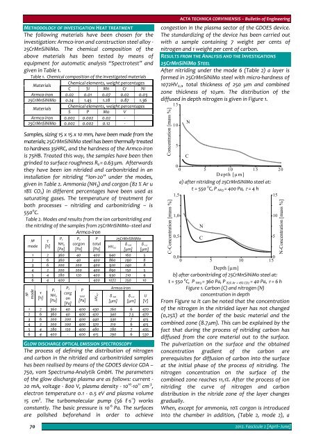
After nitriding under the mode 6 (Table 2) a layer is<br />
formed in 25CrMnSiNiMo steel with micro‐hardness of<br />
1072HV 0,1 , total thickness of 250 μm and combined<br />
zone thickness of 10μm. The distribution of the<br />
diffused in depth nitrogen is given in Figure 1.<br />
Concentration [mass %]<br />
C-Concentration [mass %]<br />
15<br />
10<br />
5<br />
N<br />
C<br />
0<br />
0 5 10 15 20<br />
Depth [µm]<br />
а) after nitriding of 25CrMnSiNiMo steel at:<br />
t = 550 0 C, P NH3 = 400 Pa, τ = 4 h<br />
1,5<br />
15<br />
1,0<br />
0,5<br />
N<br />
C<br />
0,0<br />
0<br />
0 5 10 15<br />
Depth [µm]<br />
b) after carbonitriding of 25CrMnSiNiMo steel at:<br />
t = 550 0 C, P NH3 = 360 Pa, P 82% Ar + 18% CO2 = 40 Pa, τ = 6 h<br />
Figure 1. Carbon (С) and nitrogen (N)<br />
concentration in depth<br />
From Figure 1а it can be noted that the concentration<br />
of the nitrogen in the nitrided layer has not changed<br />
(0,25%) at the border of the basic material and the<br />
combined zone (8.7μm). This can be explained by the<br />
fact that during the process of nitriding carbon has<br />
diffused from the core material out to the surface.<br />
The pulverization on the surface and the obtained<br />
concentration gradient of the carbon are<br />
prerequisites for diffusion of carbon into the surface<br />
at the initial phase of the process of nitriding. The<br />
nitrogen concentration on the surface of the<br />
combined zone reaches 11,1%. After the process of ion<br />
nitriding the curve of nitrogen and carbon<br />
distribution in the nitride zone of the layer changes<br />
gradually.<br />
When, except for ammonia, 10% corgon is introduced<br />
into the chamber in addition, (Table 2, mode 2), a<br />
10<br />
2012. Fascicule 2 [April–June]<br />
5<br />
N-Concentration [mass %]


