FortiGate IPSec VPN User Guide - FirewallShop.com
FortiGate IPSec VPN User Guide - FirewallShop.com
FortiGate IPSec VPN User Guide - FirewallShop.com

You also want an ePaper? Increase the reach of your titles
YUMPU automatically turns print PDFs into web optimized ePapers that Google loves.
Transparent mode <strong>VPN</strong>s<br />
Configure the <strong>VPN</strong> peers<br />
Configure the <strong>VPN</strong> peers<br />
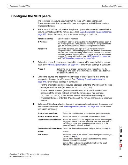
The following procedure assumes that the local <strong>VPN</strong> peer operates in<br />
Transparent mode. The remote <strong>VPN</strong> peer may operate in NAT/Route mode or<br />
Transparent mode.<br />
1 At the local <strong>FortiGate</strong> unit, define the phase 1 parameters needed to establish a<br />
secure connection with the remote peer. See “Auto Key phase 1 parameters” on<br />
page 127. Select Advanced and enter these settings in particular:<br />
Remote Gateway<br />
IP Address<br />
Advanced<br />
Select Static IP Address.<br />
Type the IP address of the public interface to the remote peer. If<br />
the remote peer is a <strong>FortiGate</strong> unit running in Transparent mode,<br />
type the IP address of the remote management interface.<br />
Select Nat-traversal, and type a value into the Keepalive<br />
Frequency field. These settings protect the headers of encrypted<br />
packets from being altered by external NAT devices and ensure<br />
that NAT address mappings do not change while the <strong>VPN</strong> tunnel<br />
is open. For more information, see “NAT traversal” on page 140<br />
and “NAT keepalive frequency” on page 140.<br />
2 Define the phase 2 parameters needed to create a <strong>VPN</strong> tunnel with the remote<br />
peer. See “Phase 2 parameters” on page 143. Enter these settings in particular:<br />
Phase 1<br />
Select the set of phase 1 parameters that you defined for the<br />
remote peer. The name of the remote peer can be selected from<br />
the Static IP Address list.<br />
3 Define the source and destination addresses of the IP packets that are to be<br />
transported through the <strong>VPN</strong> tunnel. See “Defining firewall addresses” on<br />
page 149. Enter these settings in particular:<br />
• For the originating address (source address), enter the IP address of the local<br />
management interface (for example, 10.10.10.1/32).<br />
• For the remote address (destination address), enter the IP address and<br />
netmask of the private network behind the remote peer (for example,<br />
192.168.10.0/24). If the remote peer is a <strong>FortiGate</strong> unit running in<br />
Transparent mode, enter the IP address of the remote management interface<br />
instead.<br />
4 Define an <strong>IPSec</strong> firewall policy to permit <strong>com</strong>munications between the source and<br />
destination addresses. See “Defining firewall policies” on page 150. Enter these<br />
settings in particular:<br />
Source Interface/Zone Select the local interface to the internal (private) network.<br />
Source Address Name Select the source address that you defined in Step 3.<br />
Destination Interface/Zone Select the interface to the edge router. When you configure<br />
the <strong>IPSec</strong> firewall policy on a remote peer that operates in<br />
NAT/Route mode, you select the public interface to the<br />
external (public) network instead.<br />
Destination Address Name Select the destination address that you defined in Step 3.<br />
Action<br />
IPSEC<br />
<strong>VPN</strong> Tunnel<br />
Select the name of the phase 2 tunnel configuration that you<br />
created in Step 2.<br />
Select Allow inbound to enable traffic from the remote<br />
network to initiate the tunnel.<br />
Select Allow outbound to enable traffic from the local<br />
network to initiate the tunnel.<br />
<strong>FortiGate</strong> <strong>IPSec</strong> <strong>VPN</strong> Version 3.0 <strong>User</strong> <strong>Guide</strong><br />
01-30005-0065-20070716 109