FortiGate IPSec VPN User Guide - FirewallShop.com
FortiGate IPSec VPN User Guide - FirewallShop.com
FortiGate IPSec VPN User Guide - FirewallShop.com

You also want an ePaper? Increase the reach of your titles
YUMPU automatically turns print PDFs into web optimized ePapers that Google loves.
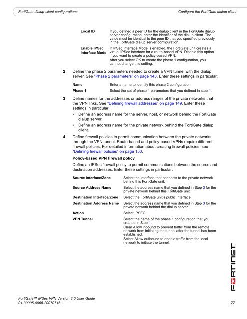
<strong>FortiGate</strong> dialup-client configurations<br />
Configure the <strong>FortiGate</strong> dialup client<br />
Local ID<br />
Enable <strong>IPSec</strong><br />
Interface Mode<br />
If you defined a peer ID for the dialup client in the <strong>FortiGate</strong> dialup<br />
server configuration, enter the identifier of the dialup client. The<br />
value must be identical to the peer ID that you specified previously<br />
in the <strong>FortiGate</strong> dialup server configuration.<br />
If <strong>IPSec</strong> Interface Mode is enabled, the <strong>FortiGate</strong> unit creates a<br />
virtual <strong>IPSec</strong> interface for a route-based <strong>VPN</strong>. Disable this option<br />
if you want to create a policy-based <strong>VPN</strong>.<br />
After you select OK to create the phase 1 configuration, you<br />
cannot change this setting.<br />
2 Define the phase 2 parameters needed to create a <strong>VPN</strong> tunnel with the dialup<br />
server. See “Phase 2 parameters” on page 143. Enter these settings in particular:<br />
Name<br />
Enter a name to identify this phase 2 configuration.<br />
Phase 1 Select the set of phase 1 parameters that you defined in step 1.<br />
3 Define names for the addresses or address ranges of the private networks that<br />
the <strong>VPN</strong> links. See “Defining firewall addresses” on page 149. Enter these<br />
settings in particular:<br />
• Define an address name for the server, host, or network behind the <strong>FortiGate</strong><br />
dialup server.<br />
• Define an address name for the private network behind the <strong>FortiGate</strong> dialup<br />
client.<br />
4 Define firewall policies to permit <strong>com</strong>munication between the private networks<br />
through the <strong>VPN</strong> tunnel. Route-based and policy-based <strong>VPN</strong>s require different<br />
firewall policies. For detailed information about creating firewall policies, see<br />
“Defining firewall policies” on page 150.<br />
Policy-based <strong>VPN</strong> firewall policy<br />
Define an <strong>IPSec</strong> firewall policy to permit <strong>com</strong>munications between the source and<br />
destination addresses. Enter these settings in particular:<br />
Source Interface/Zone<br />
Source Address Name<br />
Destination Interface/Zone<br />
Destination Address Name<br />
Action<br />
<strong>VPN</strong> Tunnel<br />
Select the interface that connects to the private network<br />
behind this <strong>FortiGate</strong> unit.<br />
Select the address name that you defined in Step 3 for the<br />
private network behind this <strong>FortiGate</strong> unit.<br />
Select the <strong>FortiGate</strong> unit’s public interface.<br />
Select the address name that you defined in Step 3 for the<br />
private network behind the dialup server.<br />
Select IPSEC.<br />
Select the name of the phase 1 configuration that you<br />
created in Step 1.<br />
Clear Allow inbound to prevent traffic from the remote<br />
network from initiating the tunnel after the tunnel has been<br />
established.<br />
Select Allow outbound to enable traffic from the local<br />
network to initiate the tunnel.<br />
<strong>FortiGate</strong> <strong>IPSec</strong> <strong>VPN</strong> Version 3.0 <strong>User</strong> <strong>Guide</strong><br />
01-30005-0065-20070716 77