- Page 2 and 3:
The Illustrated Dictionary of Elect
- Page 4 and 5:
The Illustrated Dictionary of Elect
- Page 6 and 7:
To Tony, Tim, and Samuel from Uncle
- Page 8 and 9:
Contents Preface ix Acknowledgments
- Page 10 and 11:
Preface The Illustrated Dictionary
- Page 12 and 13:
Acknowledgments Illustrations in th
- Page 14 and 15:
The Illustrated Dictionary of Elect
- Page 16 and 17:
A 1. Symbol for GAIN. 2. Symbol for
- Page 18 and 19:
absolute error • absolute toleran
- Page 20 and 21:
abvolt • accentuation 5 abvolt Th
- Page 22 and 23:
accw • ac magnetic bias 7 accw Ab
- Page 24 and 25:
acoustic feedback • acoustic radi
- Page 26 and 27:
ac plate voltage • active chord m
- Page 28 and 29:
active satellite • adapter 13 act
- Page 30 and 31:
address indirect • adjusted decib
- Page 32 and 33:
AFIPS • aircraft bonding 17 AFIPS
- Page 34 and 35:
airwaves • aliasing noise 19 mist
- Page 36 and 37:
alloy diode • alternating-charge
- Page 38 and 39:
amateur radio • AM/FM tuner 23 am
- Page 40 and 41:
amp-hr • amplify 25 Wire axis Dir
- Page 42 and 43:
amplitude separator • analog inte
- Page 44 and 45:
Anderson bridge • angle of beam 2
- Page 46 and 47:
anhysteretic state • anomalous pr
- Page 48 and 49:
antenna ground system The earth, co
- Page 50 and 51: anthropomorphism • antiparticle 3
- Page 52 and 53: apogee • arc cosecant 37 apogee 1
- Page 54 and 55: area code • arithmetic symmetry 3
- Page 56 and 57: ARSR • assemble 41 ARSR Abbreviat
- Page 58 and 59: astronomical unit • atmospheric a
- Page 60 and 61: atomic reactor • attracted-disk e
- Page 62 and 63: audio-frequency meter • audio mix
- Page 64 and 65: auroral propagation • automatic c
- Page 66 and 67: automatic interrupt • automatic s
- Page 68 and 69: auxiliary equipment • avalanche b
- Page 70 and 71: axial leads • azusa 55 axial lead
- Page 72 and 73: ackbone • back resistance 57 back
- Page 74 and 75: Bakelite • balanced low-pass filt
- Page 76 and 77: alun • bandstop 61 usually provid
- Page 78 and 79: ar meter • baseband frequency res
- Page 80 and 81: asic frequency • battery 65 basic
- Page 82 and 83: eacon • beam parametric amplifier
- Page 84 and 85: eat note • Be0 69 beat note The s
- Page 86 and 87: iased search • bifilar electromet
- Page 88 and 89: BiMOS • binaural 73 BiMOS A combi
- Page 90 and 91: iofeedback monitor • Birmingham w
- Page 92 and 93: lack box • bleeder resistor 77 a
- Page 94 and 95: looper 1. A radio receiver that is
- Page 96 and 97: Boltzmann’s principle • booster
- Page 98 and 99: ow-tie test • brass pounder 83 ve
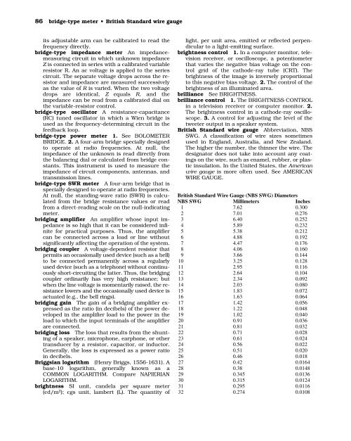
- Page 102 and 103: British thermal unit • broad resp
- Page 104 and 105: ubble memory • bulk effect 89 net
- Page 106 and 107: urst generator • button microphon
- Page 108 and 109: C 1. Abbreviation of CAPACITANCE. 2
- Page 110 and 111: calibrated triggered sweep • CAN
- Page 112 and 113: capacitive diaphragm • capacitive
- Page 114 and 115: carbon-button amplifier • cardist
- Page 116 and 117: carrier mobility Symbol, µ. In a s
- Page 118 and 119: cascaded carry • cathode 103 casc
- Page 120 and 121: cavity magnetron • cell constant
- Page 122 and 123: center-tapped inductor • ceramic-
- Page 124 and 125: change tape • character density 1
- Page 126 and 127: charge carrier • checking program
- Page 128 and 129: chirp • chopper power supply 113
- Page 130 and 131: chrominance primary • circuit dia
- Page 132 and 133: circular mil • class-A amplifier
- Page 134 and 135: click method • closed-circuit sec
- Page 136 and 137: CMRR • coaxial capacitor 121 CMRR
- Page 138 and 139: code • coherence 123 letters, num
- Page 140 and 141: cold rolling • collector voltage
- Page 142 and 143: color generator • color spectrum
- Page 144 and 145: coma lobes • commercial data proc
- Page 146 and 147: common-mode input circuit • commu
- Page 148 and 149: compatibility • compensation theo
- Page 150 and 151:
complementer • component 135 comp
- Page 152 and 153:
compress • computer graphics 137
- Page 154 and 155:
condenser microphone • conductor
- Page 156 and 157:
conic sections • constant-current
- Page 158 and 159:
contactor noise • Continuous Comm
- Page 160 and 161:
control circuit 1. A circuit in whi
- Page 162 and 163:
convergence phase control • coord
- Page 164 and 165:
cordless mouse • corner reflector
- Page 166 and 167:
corruption • counterpoise 151 cor
- Page 168 and 169:
CQ • critical field 153 CQ A gene
- Page 170 and 171:
cross modulation • cryotron 155 t
- Page 172 and 173:
crystal loudspeaker • crystal tes
- Page 174 and 175:
current attenuation • current rel
- Page 176 and 177:
cutoff frequency • cyclic variati
- Page 178 and 179:
D 1. Symbol for DEUTERIUM. 2. Symbo
- Page 180 and 181:
data analysis display unit • data
- Page 182 and 183:
daylight lamp • dc converter 167
- Page 184 and 185:
dc plate voltage • dead band 169
- Page 186 and 187:
decade counter • decimal code 171
- Page 188 and 189:
decommutator • definite-purpose c
- Page 190 and 191:
degenerate semiconductor • deka-
- Page 192 and 193:
delay timer • demodulator 177 del
- Page 194 and 195:
depth of discharge • designation
- Page 196 and 197:
deviation ratio In a frequency-modu
- Page 198 and 199:
diamond stylus • dielectric const
- Page 200 and 201:
Dietzhold network • differential
- Page 202 and 203:
differentiate • diffused sound 18
- Page 204 and 205:
digital computer • digital repres
- Page 206 and 207:
digit filter • diode-capacitor me
- Page 208 and 209:
diode peak voltmeter • diplex rec
- Page 210 and 211:
direct-conversion receiver • dire
- Page 212 and 213:
directional wattmeter • directivi
- Page 214 and 215:
direct scanning • discrete capaci
- Page 216 and 217:
disk coil • display loss 201 disk
- Page 218 and 219:
distance mark • distributed compo
- Page 220 and 221:
diversity reception • DNL 205 div
- Page 222 and 223:
doohickey • dot 207 doohickey A u
- Page 224 and 225:
double-coil direction finder A radi
- Page 226 and 227:
double-sideband transmitter • dou
- Page 228 and 229:
1. To excite (i.e., to supply with
- Page 230 and 231:
drop-tracks • dry flashover volta
- Page 232 and 233:
dual diode • Duant electrometer 2
- Page 234 and 235:
dumping • dust cover 219 dumping
- Page 236 and 237:
dynamic decay • dynamic range 221
- Page 238 and 239:
dynatron frequency meter • dyspro
- Page 240 and 241:
E avg • echo 225 Symbol for AVERA
- Page 242 and 243:
eddy-current loss • effective aco
- Page 244 and 245:
effective phase angle • eight-lev
- Page 246 and 247:
electret microphone • electrical
- Page 248 and 249:
electrical transducer • electric
- Page 250 and 251:
electric generator • electric res
- Page 252 and 253:
electrobath • electrode efficienc
- Page 254 and 255:
electrokinetics • electrolytic el
- Page 256 and 257:
electromagnetic energy conversion
- Page 258 and 259:
electromechanical • electromigrat
- Page 260 and 261:
electron gun • electronic counter
- Page 262 and 263:
electronic hygrometer • electroni
- Page 264 and 265:
electronic watch • electron strea
- Page 266 and 267:
electrophorus • electrostatic fie
- Page 268 and 269:
electrostatic transducer • elemen
- Page 270 and 271:
EM • emissivity 255 EM 1. Abbrevi
- Page 272 and 273:
empirical design • end feed 257 t
- Page 274 and 275:
end point • energy-level diagram
- Page 276 and 277:
entladungsstrahlen • epitaxial de
- Page 278 and 279:
equatorial orbit • equivalent ind
- Page 280 and 281:
equivalent wye • error correction
- Page 282 and 283:
ETC • even-line field 267 ETC Abb
- Page 284 and 285:
exciter • expandable 269 exciter
- Page 286 and 287:
exponential horn • external dampi
- Page 288 and 289:
extreme • E zone 273 quantity. 2.
- Page 290 and 291:
fader • fan-out 275 tomotive high
- Page 292 and 293:
fatigue • feedback factor 277 bod
- Page 294 and 295:
FE-EL • ferrite limiter 279 FE-EL
- Page 296 and 297:
FET current meter • field coil 28
- Page 298 and 299:
filament • filler 283 filament In
- Page 300 and 301:
filter transmission band • firing
- Page 302 and 303:
fixed-frequency oscillator • flan
- Page 304 and 305:
flat top • flight telerobotic ser
- Page 306 and 307:
floating probe • fluorescent mate
- Page 308 and 309:
flyback transformer • focal lengt
- Page 310 and 311:
folded pattern • fork oscillator
- Page 312 and 313:
FOSDIC • fps system of units 297
- Page 314 and 315:
Fraunhofer region • frequency ban
- Page 316 and 317:
frequency function • frequency re
- Page 318 and 319:
front contact The movable contact o
- Page 320 and 321:
full-scale symmetry • function ge
- Page 322 and 323:
G 1. Symbol for CONDUCTANCE. 2. Abb
- Page 324 and 325:
gamma section • gaseous voltage r
- Page 326 and 327:
gated buffer • Gauss’ theorem 3
- Page 328 and 329:
General Packet Radio Service • ge
- Page 330 and 331:
GIGO • glucinium 315 input to a c
- Page 332 and 333:
Graffiti • graphic panel 317 a ha
- Page 334 and 335:
greatest lower bound • grid resis
- Page 336 and 337:
ground connection • ground-mounte
- Page 338 and 339:
groundtrack • G-string antenna 32
- Page 340 and 341:
Gunnplexer • G-Y signal 325 erabl
- Page 342 and 343:
half-bridge • half-wavelength 327
- Page 344 and 345:
Hall generator • handoff 329 Hall
- Page 346 and 347:
hard wiring • harmonic-distortion
- Page 348 and 349:
hat • head room 333 hat 1. Also c
- Page 350 and 351:
heat transfer • helical antenna 3
- Page 352 and 353:
Herschel-Quincke tube • heterodyn
- Page 354 and 355:
high-energy materials • high orde
- Page 356 and 357:
hiss filter • hole injector 341 h
- Page 358 and 359:
horizon • horizontal flowcharting
- Page 360 and 361:
horizontal sync pulse • hot line
- Page 362 and 363:
HSM • Huygens’ principle 347 HS
- Page 364 and 365:
hygroscopic material • hyperpolar
- Page 366 and 367:
hysteresis heater • Hz 351 hyster
- Page 368 and 369:
ID • IEC 353 Object Deflecting co
- Page 370 and 371:
illuminated switch • image transf
- Page 372 and 373:
impedance-matching transformer •
- Page 374 and 375:
inclusive-OR • indexing 359 each
- Page 376 and 377:
indoor antenna • induction modula
- Page 378 and 379:
inductive trimmer • inertial guid
- Page 380 and 381:
information superhighway • inheri
- Page 382 and 383:
input • input/output module 367 i
- Page 384 and 385:
insect robot • instantaneous spee
- Page 386 and 387:
instrument transformer • Integrat
- Page 388 and 389:
interactive photovoltaic system •
- Page 390 and 391:
intermittent commercial and amateur
- Page 392 and 393:
interpreter • intrinsic conductio
- Page 394 and 395:
inverse voltage • invister 379 ne
- Page 396 and 397:
ionization trail • I RF 381 ioniz
- Page 398 and 399:
ISDN • isoplanar 383 ISDN Abbrevi
- Page 400 and 401:
J 1. Abbreviation for JOULE. 2. Sym
- Page 402 and 403:
jogging • J rule 387 jogging Rapi
- Page 404 and 405:
K 1. General symbol for CONSTANT. 2
- Page 406 and 407:
keyboard keyer • keying speed 391
- Page 408 and 409:
kilogram-meter • kite-supported a
- Page 410 and 411:
Kraus antenna • kWh 395 +− A RF
- Page 412 and 413:
ladder network • lamp driver 397
- Page 414 and 415:
lapping • laser diode 399 lapping
- Page 416 and 417:
launching • LC 401 Input Z Z Z la
- Page 418 and 419:
lead-in • least-significant digit
- Page 420 and 421:
level-0 security • life 405 willi
- Page 422 and 423:
light load • light sensor 407 lig
- Page 424 and 425:
linear amplifier • linear scale 4
- Page 426 and 427:
line filter • linkage 411 power c
- Page 428 and 429:
liquid-pressure control • lm-hr 4
- Page 430 and 431:
loading factor • local side 415 l
- Page 432 and 433:
log e • logic probe 417 log e Abb
- Page 434 and 435:
long-term input offset voltage stab
- Page 436 and 437:
lowest usable frequency • low pow
- Page 438 and 439:
lug • LZT 423 contact attached to
- Page 440 and 441:
macro- • magnetic balance 425 mac
- Page 442 and 443:
magnetic field strength • magneti
- Page 444 and 445:
magnetic shielding • magnetic whi
- Page 446 and 447:
magnetostriction • main memory 43
- Page 448 and 449:
manual • maser 433 book, or a set
- Page 450 and 451:
matching pad An inductance-capacita
- Page 452 and 453:
Maxwell’s equations • measurand
- Page 454 and 455:
medium tension • meltback transis
- Page 456 and 457:
mercury delay line • meson 441 me
- Page 458 and 459:
meteorology • metrology 443 meteo
- Page 460 and 461:
microcomputer • micromodule 445 m
- Page 462 and 463:
microsystems electronics • midran
- Page 464 and 465:
millirutherford • minor lobe 449
- Page 466 and 467:
mixture • moderator 451 Input1 In
- Page 468 and 469:
modulation capability • modulator
- Page 470 and 471:
molecular conductance • monitor s
- Page 472 and 473:
Monte Carlo method • motorboating
- Page 474 and 475:
M scan • multiband receiver 459 b
- Page 476 and 477:
multiphase system • multiplex ste
- Page 478 and 479:
multipurpose meter • Musical Inst
- Page 480 and 481:
Mylar capacitor • myriametric wav
- Page 482 and 483:
nanowatt • natural frequency 467
- Page 484 and 485:
near ultraviolet • negative expon
- Page 486 and 487:
negative resistance • nemo 471 vo
- Page 488 and 489:
neper • network analog 473 on com
- Page 490 and 491:
neutrodon • nickel-iron 475 neutr
- Page 492 and 493:
no-charge machine fault time • no
- Page 494 and 495:
noise reduction • nominal value 4
- Page 496 and 497:
nonillion • nonoscillating detect
- Page 498 and 499:
nonsynchronous vibrator • normal-
- Page 500 and 501:
notch sweep • n-type conduction 4
- Page 502 and 503:
null frequency • N zone 487 nucle
- Page 504 and 505:
occultation • odometry 489 netic
- Page 506 and 507:
ohmic contact • oil diffusion pum
- Page 508 and 509:
one output • on-state current 493
- Page 510 and 511:
open-fuse cutout • open-wire tran
- Page 512 and 513:
operating station • optical chara
- Page 514 and 515:
optical sound recording • Orange
- Page 516 and 517:
orthoacoustic recording • oscilla
- Page 518 and 519:
oscillatory current • out of phas
- Page 520 and 521:
output current • output transform
- Page 522 and 523:
overdrive • overload recovery tim
- Page 524 and 525:
oxide-coated cathode • ozone moni
- Page 526 and 527:
packet switching • panel meter 51
- Page 528 and 529:
parallel circuit • parallel opera
- Page 530 and 531:
parallel-wire line • parasitic ca
- Page 532 and 533:
passband • passive reflector 517
- Page 534 and 535:
P band • peak envelope power 519
- Page 536 and 537:
peak torque • PEP transistor 521
- Page 538 and 539:
peripheral equipment • persistor
- Page 540 and 541:
phase compensation • phase opposi
- Page 542 and 543:
phasing capacitor • phonetic alph
- Page 544 and 545:
phosphorescence • photoelectric e
- Page 546 and 547:
photograph reception • photon 531
- Page 548 and 549:
pickoff • Pierce oscillator 533 t
- Page 550 and 551:
pincushion • pitch 535 pincushion
- Page 552 and 553:
{ plasma length • plated magnetic
- Page 554 and 555:
plate voltage • plug-in meter 539
- Page 556 and 557:
point defect • polarization 541 i
- Page 558 and 559:
polarizing filter • polygraph 543
- Page 560 and 561:
positional notation • positive gh
- Page 562 and 563:
positive temperature coefficient
- Page 564 and 565:
power-amplifier device • power gr
- Page 566 and 567:
power switch • preamplifier 551 +
- Page 568 and 569:
preset element • primary coil 553
- Page 570 and 571:
print • private branch exchange 5
- Page 572 and 573:
program • promethium cell 557 (th
- Page 574 and 575:
protective resistor • pseudo-inst
- Page 576 and 577:
pull-in voltage • pulse droop 561
- Page 578 and 579:
pulse train • purity control 563
- Page 580 and 581:
push-push multiplier • PZT 565 In
- Page 582 and 583:
QC • quad 567 QC Abbreviation of
- Page 584 and 585:
quadripartite • quantized pulse m
- Page 586 and 587:
quarter wavelength • quartz plate
- Page 588 and 589:
quick-break switch • QWERTY 573 q
- Page 590 and 591:
adar • radial 575 acronym for rad
- Page 592 and 593:
adioactive element • radio-freque
- Page 594 and 595:
adiolocator • radio spectroscope
- Page 596 and 597:
adiothermy • random feed 581 radi
- Page 598 and 599:
atio detector • reactance 583 dio
- Page 600 and 601:
eadthrough • receiver front end 5
- Page 602 and 603:
ecompile • rectified alternating
- Page 604 and 605:
eductionism • reflected power 589
- Page 606 and 607:
efractivity • rejection filter 59
- Page 608 and 609:
eluctivity • replacement 593 relu
- Page 610 and 611:
esin • resistance-inductance circ
- Page 612 and 613:
esistor substitution box • resona
- Page 614 and 615:
everberation time • revolution 59
- Page 616 and 617:
Rieke chart • ripple 601 ultra-hi
- Page 618 and 619:
ock • rotary beam 603 rock Slang
- Page 620 and 621:
ounding • rumble 605 yields 3.5.
- Page 622 and 623:
S 1. Symbol for SCREEN GRID of a va
- Page 624 and 625:
saturation • scale down 609 the s
- Page 626 and 627:
scan rate • scientific notation 6
- Page 628 and 629:
sea clutter • secondary frequency
- Page 630 and 631:
secular equilibrium • selective f
- Page 632 and 633:
self-excited oscillator • self-su
- Page 634 and 635:
semitone • sequential 619 semiton
- Page 636 and 637:
series-fed amplifier • serrated r
- Page 638 and 639:
sexagesimal number system • shaft
- Page 640 and 641:
shock-excited oscillator • short
- Page 642 and 643:
S/I • sidetone 627 S/I Abbreviati
- Page 644 and 645:
signal rectifier • silicon capaci
- Page 646 and 647:
silver-oxide cell • single cotton
- Page 648 and 649:
single-line tap • single-track re
- Page 650 and 651:
skin effect • slider 635 skin eff
- Page 652 and 653:
slotted line • small signal 637 w
- Page 654 and 655:
smoke detector • software 639 Som
- Page 656 and 657:
soldering gun • solution 641 typi
- Page 658 and 659:
sound • sound power level 643 sou
- Page 660 and 661:
source impedance • special charac
- Page 662 and 663:
speech clipping • speed of transm
- Page 664 and 665:
spiral-rod oscillator • spot modu
- Page 666 and 667:
square-law meter • ssc 651 deflec
- Page 668 and 669:
staggered tuning • standard signa
- Page 670 and 671:
statement • statics 655 statement
- Page 672 and 673:
step-down ratio • stop amplifier
- Page 674 and 675:
storage temperature • stray field
- Page 676 and 677:
stylus pressure • subsidiary comm
- Page 678 and 679:
S units • supermodulation 663 V 1
- Page 680 and 681:
surface-barrier transistor • surv
- Page 682 and 683:
swinging choke • symmetrical cond
- Page 684 and 685:
synchronous computer • synthesize
- Page 686 and 687:
T 1. Symbol for TRANSFORMER. 2. Abb
- Page 688 and 689:
tap changer • target acquisition
- Page 690 and 691:
tee junction • telephone amplifie
- Page 692 and 693:
television • temperature derating
- Page 694 and 695:
terrestrial magnetism • texture s
- Page 696 and 697:
thermal switch • thermoelectric j
- Page 698 and 699:
thin-film semiconductor • three-p
- Page 700 and 701:
thy • time-interval mode 685 thy
- Page 702 and 703:
tolerance • torque amplifier 687
- Page 704 and 705:
transceiver 1. A combination transm
- Page 706 and 707:
transient suppressor • transistor
- Page 708 and 709:
transverse electric mode • triang
- Page 710 and 711:
Trinitron • tropospheric propagat
- Page 712 and 713:
tuned-collector oscillator • tunn
- Page 714 and 715:
two-phase • Type A telephone line
- Page 716 and 717:
UHF generator • ultra-low frequen
- Page 718 and 719:
ultrasonic light modulator • ultr
- Page 720 and 721:
unblanking pulse • unconditional
- Page 722 and 723:
underload relay • unequal alterna
- Page 724 and 725:
unidirectional speaker • unilater
- Page 726 and 727:
unit record • universal-wound coi
- Page 728 and 729:
unsaturated standard cell • ununo
- Page 730 and 731:
uranium rays • UVM 715 observed t
- Page 732 and 733:
vacuum level • V antenna 717 vacu
- Page 734 and 735:
variable inductor • VATE 719 Seve
- Page 736 and 737:
vector power factor • velocity mo
- Page 738 and 739:
versed sine • vertical frequency
- Page 740 and 741:
vestigial sideband 1. A portion of
- Page 742 and 743:
vibrograph • video IF amplifier 7
- Page 744 and 745:
vinylidene chloride • visible spe
- Page 746 and 747:
voice-frequency carrier telegraphy
- Page 748 and 749:
voltage doubler • voltage peak 73
- Page 750 and 751:
voltage-sensitive capacitor • vol
- Page 752 and 753:
volume magnetostriction • vy 737
- Page 754 and 755:
wall absorption • water adsorptio
- Page 756 and 757:
watt • wave direction 741 watt Ab
- Page 758 and 759:
waveguide flange • waveguide tee
- Page 760 and 761:
wave normal • way station 745 a r
- Page 762 and 763:
welder 1. An electrical device, oft
- Page 764 and 765:
whistle filter • Wide Area Teleph
- Page 766 and 767:
width modulation • Wilson cloud c
- Page 768 and 769:
wing • wire gauge 753 another mem
- Page 770 and 771:
wire stripper • Wolf’s equation
- Page 772 and 773:
workout • wrong color 757 workout
- Page 774 and 775:
X 1. Symbol for REACTANCE. 2. Symbo
- Page 776 and 777:
X-ray photograph • x-y recorder 7
- Page 778 and 779:
y-axis • ytterbium metals 763 2.
- Page 780 and 781:
Z 1. Symbol for IMPEDANCE. 2. Symbo
- Page 782 and 783:
Zener knee • zero capacitance 767
- Page 784 and 785:
zero potential • zero-zero 769 ze
- Page 786 and 787:
Z meter • zwitterion 771 (3) an i
- Page 788 and 789:
Appendix Schematic symbols A Ammete
- Page 790 and 791:
Schematic symbols 775 Diode, PIN Di
- Page 792 and 793:
Schematic symbols 777 Inductor, pow
- Page 794 and 795:
Schematic symbols 779 Plug, two-wir
- Page 796 and 797:
Schematic symbols 781 Solar cell
- Page 798 and 799:
Schematic symbols 783 Transformer,
- Page 800 and 801:
Schematic symbols 785 Tube, triode
- Page 802 and 803:
788 Appendix B System cgs cgs Prope
- Page 804 and 805:
790 Appendix B @ at the rate of; at
- Page 806 and 807:
This page intentionally left blank.
- Page 808 and 809:
This page intentionally left blank.
- Page 810:
Suggested additional references Cro


