Super Smart Ball Bushing Bearing - Hollin Applications
Super Smart Ball Bushing Bearing - Hollin Applications
Super Smart Ball Bushing Bearing - Hollin Applications

You also want an ePaper? Increase the reach of your titles
YUMPU automatically turns print PDFs into web optimized ePapers that Google loves.
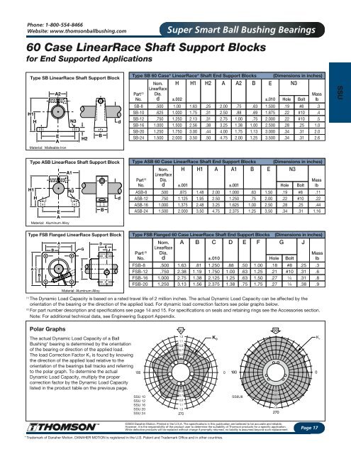
Phone: 1-800-554-8466Website: www.thomsonballbushing.com<strong>Super</strong> <strong>Smart</strong> <strong>Ball</strong> <strong>Bushing</strong> <strong>Bearing</strong>s60 Case LinearRace Shaft Support Blocksfor End Supported <strong>Applications</strong>Type SB LinearRace Shaft Support BlockH1HA2EAMaterial: Malleable IronN3H2BdType SB 60 Case* LinearRace* Shaft End Support BlocksH H1 H2 A A2 BPart (2)No.Nom.LinearRaceDia.d±.002SB-8 .500 1.00 1.63 .25 2.00 .75SB-10 .625 1.000 1.75 .31 2.50 .88SB-12 .750 1.250 2.13 .31 2.75 1.00SB-16 1.000 1.500 2.56 .38 3.25 1.38SB-20 1.250 1.750 3.00 .44 4.00 1.75SB-24 1.500 2.000 3.50 .50 4.75 2.00.63.69.751.001.131.25(Dimensions in inches)E N3±.0101.5001.8752.0002.5003.0003.500Hole.19.22.22.28.34.34Bolt#8#10#10.25.31.31Masslb.3.4.51.02.02.6SSUType ASB LinearRace Shaft Support BlockH1HEAMaterial: Aluminum AlloyA1N3BdType ASB 60 Case LinearRace Shaft End Support BlocksH H1 A A1 BPart (2)No.ASB-8ASB-12Nom.LinearRaceDia.d.500.7501.000±.001±.001.8751.1251.481.952.002.501.0001.250.63.75ASB-16 1.375 2.48 3.25 1.625 1.00ASB-24 1.500 2.000 3.50 4.75 2.375 1.25E1.502.002.503.50(Dimensions in inches)N3Hole.19.22.28.34Bolt#8#10.25.31Masslb.11.22.441.16Type FSB Flanged LinearRace Support BlockBBACA C FGMaterial: Aluminum AlloyDEJType FSB Flanged 60 Case LinearRace Shaft End Support BlocksA B C D E FPart (2)No.FSB-8FSB-12Nom.LinearRaceDia.d.500 1.63 .81 1.250 .88.750 2.38 1.19 1.750 1.00FSB-16 1.000 2.75 1.38 2.125 1.25FSB-20 1.250 3.13 1.56 2.375 1.38(1)The Dynamic Load Capacity is based on a rated travel life of 2 million inches. The actual Dynamic Load Capacity can be affected by theorientation of the bearing or the direction of the applied load. For dynamic load correction factors see polar graphs below.(2)For part number description and specifications see page 14 and 15. For specifications on seals and retaining rings see the Accessories section.Note: For additional technical data, see Engineering Support Appendix.±.010.50.63.63.751.001.251.501.75(Dimensions in inches)G JHole.18.21.27.27Bolt#8#101⁄41 ⁄4.25.31.31.38Masslb.3.6.8.9Polar GraphsThe actual Dynamic Load Capacity of a <strong>Ball</strong><strong>Bushing</strong>* bearing is determined by the orientationof the bearing or direction of the applied load.The load Correction Factor K 0 is found by knowingthe direction of the applied load relative to theorientation of the bearings ball tracks and referringto the polar graph. To determine the actualDynamic Load Capacity, multiply the propercorrection factor by the Dynamic Load Capacitylisted in the product table on the previous page.SSU 10SSU 12SSU 16SSU 20SSU 24K 01800SS6U8900,60,70,80,91,0270K o©2003 Danaher Motion. Printed in the U.S.A. The specifications in this publication are believed to be accurate and reliable.However, it is the responsibility of the product user to determine the suitability of Thomson products for a specific application.While defective products will be replaced without charge if promptly returned, no liability is assumed beyond such replacement.Page 17* Trademark of Danaher Motion. DANAHER MOTION is registered in the U.S. Patent and Trademark Office and in other countries.