Super Smart Ball Bushing Bearing - Hollin Applications
Super Smart Ball Bushing Bearing - Hollin Applications
Super Smart Ball Bushing Bearing - Hollin Applications

Create successful ePaper yourself
Turn your PDF publications into a flip-book with our unique Google optimized e-Paper software.
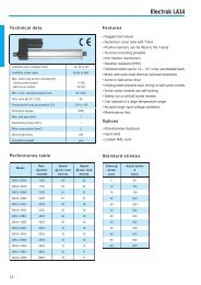
Phone: 1-800-554-8466Website: www.thomsonballbushing.comPrecision Steel <strong>Ball</strong> <strong>Bushing</strong> <strong>Bearing</strong>sMiniature Instrument <strong>Ball</strong> <strong>Bushing</strong> <strong>Bearing</strong>and 60 Case LinearRace SetsType SB LinearRace Support BlockA2H1HN3dType SB 60 Case* LinearRace* End Support Blocks(Dimensions in inches)H H1 H2 A A2 B E N3PartNo.NominalLinearRaceDiameterd±.002±.010HoleBoltMasslbSB-4 .250 .687 1.06 .25 1.50 .63 .50 1.125 .16 #6 .03EAH2Material: Malleable Iron for sizes .5 to 2 in.Aluminum Alloy for sizes .25 and .375 in.Material: Aluminum AlloyBH1HType ASB LinearRace Support BlockEAMaterial: Aluminum AlloyA1N3Part Number DescriptionINST 2 MS1 x L3.0Instrument<strong>Ball</strong> <strong>Bushing</strong> ProductBd60 Case LinearRacediameter2=1/8 in., 3=3/16 in.or 4=1/4 in.Type ASB 60 Case LinearRace End Support BlocksNominal H H1 A A1 BLinearRacePart DiameterNo. d ±.001±.001ASB-4 .250 .500 .88 1.50 .750 .50Length of 60 Case LinearRacein inches (3.0 in.)Type of matched set• MS1 - one bearing andone 60 Case LinearRace• MS2 - two bearings andone 60 Case LinearRace(Dimensions in inches)E N3MassHole Bolt lb1.12 .16 #6 .0660 Case LinearRace SpecificationsMaterial: 440C Stainless SteelHardness: 55 HRC minimumSurface Finish: 4 R a microinchStraightness: .0001 inch per inchPRECISION(1)The Dynamic Load Capacity is based on a rated travel life of 2 million inches.The actual Dynamic Load Capacity can be affected by the orientation of the bearing or the direction of the applied load. For dynamic loadcorrection factors see polar graphs below. The dynamic load capacity for MS2 configurations are based on two bearings equally loaded.Note: For additional technical data, see Engineering Support Appendix.Polar GraphThe actual Dynamic Load Capacity of a <strong>Ball</strong> <strong>Bushing</strong> bearing isdetermined by the orientation of the bearing or direction of theapplied load. The load Correction Factor K 0 is found by knowingthe direction of the applied load relative to the orientation of thebearings ball tracks and referring to the polar graph. To determinethe actual Dynamic Load Capacity, multiply the propercorrection factor by the Dynamic Load Capacity listed in theproduct table on the previous page.K 0©2003 Danaher Motion. Printed in the U.S.A. The specifications in this publication are believed to be accurate and reliable.However, it is the responsibility of the product user to determine the suitability of Thomson products for a specific application.While defective products will be replaced without charge if promptly returned, no liability is assumed beyond such replacement.Page 83* Trademark of Danaher Motion. DANAHER MOTION is registered in the U.S. Patent and Trademark Office and in other countries.