Linear Positioners Catalog_en-US_revA - Kollmorgen
Linear Positioners Catalog_en-US_revA - Kollmorgen
Linear Positioners Catalog_en-US_revA - Kollmorgen

Create successful ePaper yourself
Turn your PDF publications into a flip-book with our unique Google optimized e-Paper software.
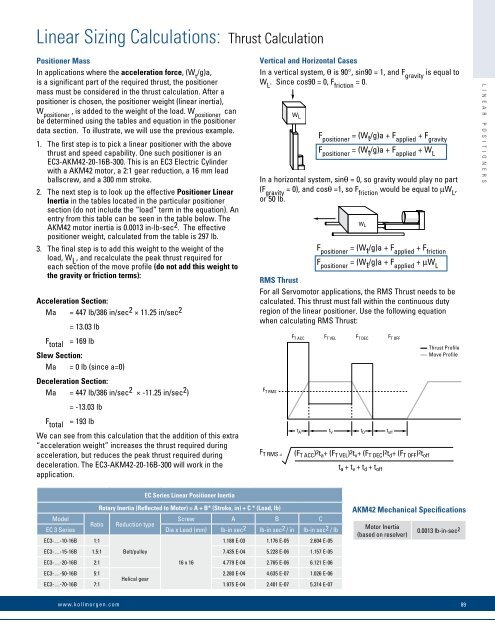
<strong>Linear</strong> Sizing Calculations: Thrust CalculationPositioner MassIn applications where the acceleration force, (W t /g)a,is a significant part of the required thrust, the positionermass must be considered in the thrust calculation. After apositioner is chos<strong>en</strong>, the positioner weight (linear inertia),W positioner , is added to the weight of the load. W positioner canbe determined using the tables and equation in the positionerdata section. To illustrate, we will use the previous example.1. The first step is to pick a linear positioner with the abovethrust and speed capability. One such positioner is anEC3-AKM42-20-16B-300. This is an EC3 Electric Cylinderwith a AKM42 motor, a 2:1 gear reduction, a 16 mm leadballscrew, and a 300 mm stroke.2. The next step is to look up the effective Positioner <strong>Linear</strong>Inertia in the tables located in the particular positionersection (do not include the “load” term in the equation). An<strong>en</strong>try from this table can be se<strong>en</strong> in the table below. TheAKM42 motor inertia is 0.0013 in-lb-sec 2 . The effectivepositioner weight, calculated from the table is 297 lb.3. The final step is to add this weight to the weight of theload, W L , and recalculate the peak thrust required foreach section of the move profile (do not add this weight tothe gravity or friction terms):Acceleration Section:Ma = 447 lb/386 in/sec 2 × 11.25 in/sec 2= 13.03 lbF total = 169 lbSlew Section:Ma = 0 lb (since a=0)Deceleration Section:Ma = 447 lb/386 in/sec 2 × -11.25 in/sec 2 )= -13.03 lbF total = 193 lbWe can see from this calculation that the addition of this extra“acceleration weight” increases the thrust required duringacceleration, but reduces the peak thrust required duringdeceleration. The EC3-AKM42-20-16B-300 will work in theapplication.Vertical and Horizontal CasesIn a vertical system, θ is 90°, sin90 = 1, and F gravity is equal toW L . Since cos90 = 0, F friction = 0.W LF positioner = (W t /g)a + F applied + F gravityF positioner = (W t /g)a + F applied + W LIn a horizontal system, sinθ = 0, so gravity would play no part(F gravity = 0), and cosθ =1, so F friction would be equal to µW L ,or 50 lb.F positioner = (W t /g)a + F applied + F frictionF positioner = (W t /g)a + F applied + µW LRMS ThrustFor all Servomotor applications, the RMS Thrust needs to becalculated. This thrust must fall within the continuous dutyregion of the linear positioner. Use the following equationwh<strong>en</strong> calculating RMS Thrust:W LF T RMSF T ACC F T VEL F T DEC F T OFFF T RMS =t A t V t D t off(F T ACC ) 2 t a + (F T VEL ) 2 t v + (F T DEC ) 2 t d + (F T OFF ) 2 t offt a + t v + t d + t offThrust ProfileMove ProfileL I N E A R P O S I T I O N E R SEC Series <strong>Linear</strong> Positioner InertiaRotary Inertia (Reflected to Motor) = A + B* (Stroke, in) + C * (Load, lb)ModelScrew A B CRatio Reduction typeEC 3 Series Dia x Lead (mm) lb-in sec 2 lb-in sec 2 / in lb-in sec 2 / lbEC3-…-10-16B 1:11.188 E-03 1.176 E-05 2.604 E-05EC3-…-15-16B 1.5:1 Belt/pulley7.435 E-04 5.228 E-06 1.157 E-05EC3-…-20-16B 2:1 16 x 164.779 E-04 2.765 E-06 6.121 E-06EC3-…-50-16B 5:12.280 E-04 4.635 E-07 1.026 E-06Helical gearEC3-…-70-16B 7:1 1.975 E-04 2.401 E-07 5.314 E-07AKM42 Mechanical SpecificationsMotor Inertia(based on resolver)0.0013 lb-in-sec 2www.kollmorg<strong>en</strong>.com89