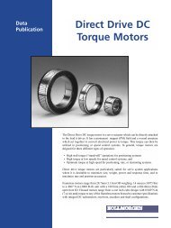
Linear Positioners Catalog_en-US_revA - Kollmorgen
Linear Positioners Catalog_en-US_revA - Kollmorgen
Linear Positioners Catalog_en-US_revA - Kollmorgen

You also want an ePaper? Increase the reach of your titles
YUMPU automatically turns print PDFs into web optimized ePapers that Google loves.
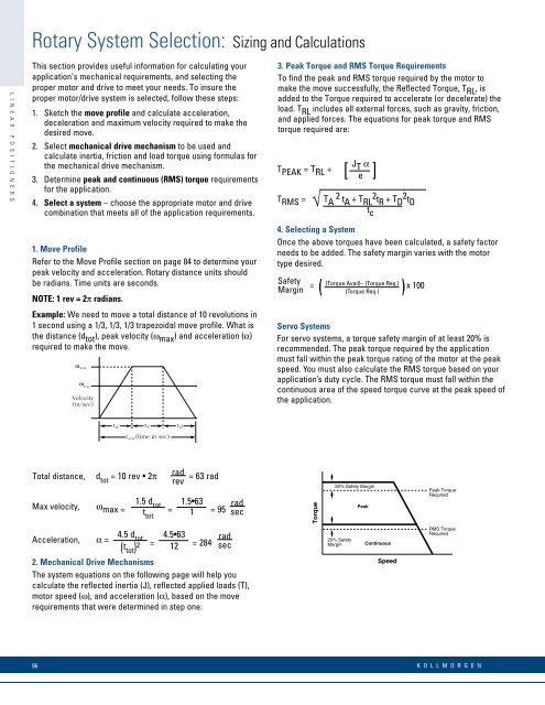
Rotary System Selection: Sizing and CalculationsL I N E A R P O S I T I O N E R SThis section provides useful information for calculating yourapplication’s mechanical requirem<strong>en</strong>ts, and selecting theproper motor and drive to meet your needs. To insure theproper motor/drive system is selected, follow these steps:1. Sketch the move profile and calculate acceleration,deceleration and maximum velocity required to make thedesired move.2. Select mechanical drive mechanism to be used andcalculate inertia, friction and load torque using formulas forthe mechanical drive mechanism.3. Determine peak and continuous (RMS) torque requirem<strong>en</strong>tsfor the application.4. Select a system – choose the appropriate motor and drivecombination that meets all of the application requirem<strong>en</strong>ts.1. Move ProfileRefer to the Move Profile section on page 84 to determine yourpeak velocity and acceleration. Rotary distance units shouldbe radians. Time units are seconds.NOTE: 1 rev = 2π radians.Example: We need to move a total distance of 10 revolutions in1 second using a 1/3, 1/3, 1/3 trapezoidal move profile. What isthe distance (d tot ), peak velocity (ω max ) and acceleration (α)required to make the move.ω maxVelocity(in/sec)3. Peak Torque and RMS Torque Requirem<strong>en</strong>tsTo find the peak and RMS torque required by the motor tomake the move successfully, the Reflected Torque, T RL , isadded to the Torque required to accelerate (or decelerate) theload. T RL includes all external forces, such as gravity, friction,and applied forces. The equations for peak torque and RMStorque required are:JT PEAK = T RL +[ T αe ]T RMS =√4. Selecting a SystemOnce the above torques have be<strong>en</strong> calculated, a safety factorneeds to be added. The safety margin varies with the motortype desired.SafetyMarginT A 2 t A + T RL2 tR + T D2 tDt c(Torque Avail)– (Torque Req.)( )(Torque Req.)= x 100Servo SystemsFor servo systems, a torque safety margin of at least 20% isrecomm<strong>en</strong>ded. The peak torque required by the applicationmust fall within the peak torque rating of the motor at the peakspeed. You must also calculate the RMS torque based on yourapplication’s duty cycle. The RMS torque must fall within thecontinuous area of the speed torque curve at the peak speed ofthe application.ω avgt v20% Safety Margint atmax(time in sec)t dTotal distance, dradtot = 10 rev • 2π = 63 radrev1.5 dMax velocity, ω tot 1.5•63max = t = = 95tot 1radsecTorquePeakPeak TorqueRequired4.5 dAcceleration, α = tot 4.5•63= = 284( radt sectot) 2 122. Mechanical Drive MechanismsThe system equations on the following page will help youcalculate the reflected inertia (J), reflected applied loads (T),motor speed (ω), and acceleration (α), based on the moverequirem<strong>en</strong>ts that were determined in step one.20% SafetyMarginContinuousSpeedRMS TorqueRequired96K O L L M O R G E N