Linear Positioners Catalog_en-US_revA - Kollmorgen
Linear Positioners Catalog_en-US_revA - Kollmorgen
Linear Positioners Catalog_en-US_revA - Kollmorgen

You also want an ePaper? Increase the reach of your titles
YUMPU automatically turns print PDFs into web optimized ePapers that Google loves.
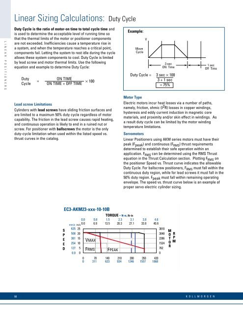
L I N E A R P O S I T I O N E R S<strong>Linear</strong> Sizing Calculations: Duty CycleDuty Cycle is the ratio of motor-on time to total cycle time andis used to determine the acceptable level of running time sothat the thermal limits of the motor or positioner compon<strong>en</strong>tsare not exceeded. Ineffici<strong>en</strong>cies cause a temperature rise ina system, and wh<strong>en</strong> the temperature reaches a critical point,compon<strong>en</strong>ts fail. Letting the system to rest idle during the cycleallows these system compon<strong>en</strong>ts to cool. Duty Cycle is limitedby lead screw and motor thermal limits. Use the followingequation and example to determine Duty Cycle:DutyCycle=ON TIMEON TIME + OFF TIME× 100Example:MoveCycleV3 secON TimeDuty Cycle = 3 sec × 1003 + 1 sec= 75%1 secOff TimeLead screw LimitationsCylinders with lead screws have sliding friction surfaces andare limited to a maximum 50% duty cycle regardless of motorcapability. The friction in the lead screw causes rapid heating,and continuous operation is likely to <strong>en</strong>d in a ruined nut orscrew. For positioner with ballscrews the motor is the onlyduty-cycle limitation wh<strong>en</strong> used within the listed speed vs.thrust curves in the catalog.Motor TypeElectric motors incur heat losses via a number of paths,namely, friction, ohmic (I 2 R) losses in copper windings,hysteresis and eddy curr<strong>en</strong>t induction in magnetic corematerials, and proximity and/or skin effect in windings. Asa result duty cycle can be limited by the motor windingtemperature limitations.Servomotors<strong>Linear</strong> <strong>Positioners</strong> using AKM series motors must have theirpeak (Fpeak) and continuous (F RMS ) thrust requirem<strong>en</strong>tsdetermined to establish their safe operation within anapplication. F RMS can be determined using the RMS Thrustequation in the Thrust Calculation section. Plotting F RMS onthe positioner Speed vs. Thrust curve indicates the allowableDuty Cycle. For ballscrew positioners, F RMS must fall within thecontinuous duty region, while for lead screws it must fall in the50% duty region. Fpeak must fall within remaining operating<strong>en</strong>velope. The speed vs. thrust curve below is an example ofproper servo electric cylinder sizing.SPEEDEC3-AKM23-xxx-10-10BTORQUE - N-m, lb-in0.0 0.8 1.5 2.3 3.1 3.8 4.6mm/s in/s 0.0 6.8 13.5 20.3 27.1 33.8 40.6635 253810508 203048381 152286VMAX254 101524127 5FRMS762FPEAK0.0 000 70 140 210 280 350 4200 311 623 934 1246 1557 1868MOTORRPMEC3-AKM23-10-10B90K O L L M O R G E N