- Page 1 and 2:
HIGH PERFORMANCE TOOLING SOLUTIONS
- Page 3 and 4:
BCV/CV SHANKS BBT/BT SHANKS HSK SHA
- Page 5 and 6:
INDEX BASIC ARBORS BASIC ARBORS BAS
- Page 7 and 8:
INDEX LARGE DIAMETER BORING INDEXAB
- Page 9 and 10:
INDEX MEASURING INSTRUMENTS MEASURI
- Page 11 and 12:
BIG-PLUS ® OVERVIEW Improvement of
- Page 13 and 14:
BIG CAPTO OVERVIEW BIG CAPTO ISO 26
- Page 15 and 16:
CK/CKB/CKN TOOLING SYSTEM OVERVIEW
- Page 17 and 18:
COLLET CHUCK PROGRAM OVERVIEW Colle
- Page 19 and 20:
R MEGA NEW BABY CHUCK OVERVIEW R CL
- Page 21 and 22:
R MEGA E CHUCK OVERVIEW R CLAMPING
- Page 23 and 24:
R MEGA PERFECT GRIP OVERVIEW MEGA P
- Page 25 and 26:
R NEW Hi-POWER MILLING CHUCK OVERVI
- Page 27 and 28:
Meets Diverse Machining Application
- Page 29 and 30:
MEGA SYNCHRO TAPPING HOLDER OVERVIE
- Page 31 and 32:
CK BORING SYSTEM TWIN CUTTERS OVERV
- Page 33 and 34:
CK FINISH BORING SYSTEM SERIES 310
- Page 35 and 36:
CK BORING SYSTEM OD TURNING OVERVIE
- Page 37 and 38:
R SMART DAMPER MILLING Integrated D
- Page 39 and 40:
R TURNING TOOLS 90º RIGHT ANGLE ST
- Page 41 and 42:
ANGLE HEAD OVERVIEW A Wide Range of
- Page 43 and 44:
R AIR POWER SPINDLE OVERVIEW AIR PO
- Page 45 and 46:
R DYNA TEST OVERVIEW DYNA TEST STAT
- Page 47 and 48:
COMPACT SENSOR SERIES OVERVIEW Quic
- Page 49 and 50:
FULLCUT MILL OVERVIEW Application E
- Page 51 and 52:
FULLCUT MILL ARBOR TYPE & SURFACE M
- Page 53 and 54:
C-CUTTER OVERVIEW Chamfering Tool H
- Page 55 and 56:
C-CUTTER BOY & BF CUTTER OVERVIEW C
- Page 57 and 58:
COLLET CHUCKS 58-62 MEGA MICRO CHUC
- Page 59 and 60:
COLLET CHUCKS MEGA NEW BABY CHUCK C
- Page 61 and 62:
COLLET CHUCKS MEGA ER GRIP CLAMPING
- Page 63 and 64:
MILLING CHUCKS MEGA DOUBLE POWER CH
- Page 65 and 66:
MILLING CHUCKS MEGA PERFECT GRIP BC
- Page 67 and 68:
MILLING CHUCKS NEW Hi-POWER MILLING
- Page 69 and 70:
ød øD øD2 øD1 HYDRAULIC CHUCKS
- Page 71 and 72:
BASIC ARBOR SHRINK FIT HOLDER CLAMP
- Page 73 and 74:
BASIC ARBORS Catalog Number BCV50-S
- Page 75 and 76:
BASIC ARBORS HIGH RIGIDITY SHELL MI
- Page 77 and 78:
BASIC ARBORS SMART DAMPER MILLING
- Page 79 and 80:
TAP HOLDERS MEGA SYNCHRO TAPPING HO
- Page 81 and 82:
MODULAR HOLDERS Catalog Number Refe
- Page 83 and 84:
MODULAR HOLDERS CKB SHANKS—WITH F
- Page 85 and 86:
MODULAR HOLDERS ABS SHANKS L A.1 BC
- Page 87 and 88:
ANGLE HEADS AG90 NBS TYPE CLAMPING
- Page 89 and 90:
ANGLE HEADS Catalog Number BCV50-AG
- Page 91 and 92:
ANGLE HEADS AG90 SLENDER DRIVE CLAM
- Page 93 and 94:
ANGLE HEADS AG90 HMC TYPE For Heavy
- Page 95 and 96:
ANGLE HEADS AGU30 TYPE CLAMPING RAN
- Page 97 and 98:
SPEED INCREASERS AIR POWER SPINDLE
- Page 99 and 100:
99 A.1 BCV/CV
- Page 101 and 102:
COOLANT INDUCERS Hi-JET HOLDER—TG
- Page 103 and 104:
ACCESSORIES DYNA TEST Helps identif
- Page 105 and 106:
105 A.1 BCV/CV
- Page 107 and 108:
COLLET CHUCKS 108-117 MEGA MICRO CH
- Page 109 and 110:
COLLET CHUCKS MEGA MICRO CHUCK CLAM
- Page 111 and 112:
COLLET CHUCKS Catalog Number ød ø
- Page 113 and 114:
COLLET CHUCKS Catalog Number ød ø
- Page 115 and 116:
COLLET CHUCKS Catalog Number ød ø
- Page 117 and 118:
COLLET CHUCKS Catalog Number BBT40-
- Page 119 and 120:
MILLING CHUCKS Catalog Number Fig.
- Page 121 and 122:
MILLING CHUCKS CYLINDRICAL SHANK WI
- Page 123 and 124:
MILLING CHUCKS Catalog Number Fig.
- Page 125 and 126:
HYDRAULIC CHUCKS Catalog Number Fig
- Page 127 and 128:
HYDRAULIC CHUCKS Catalog Number Fig
- Page 129 and 130:
HYDRAULIC CHUCKS Catalog Number Fig
- Page 131 and 132:
HYDRAULIC CHUCKS JET COOLANT TYPE C
- Page 133 and 134:
BASIC ARBORS SHRINK FIT HOLDER—SL
- Page 135 and 136:
BASIC ARBORS SIDE CUTTER ARBOR CLAM
- Page 137 and 138:
BASIC ARBORS BIG-PLUS ® Taper Cata
- Page 139 and 140:
BASIC ARBORS SMART DAMPER MILLING
- Page 141 and 142:
TAP HOLDERS MEGA SYNCHRO TAPPING HO
- Page 143 and 144:
MODULAR HOLDERS Catalog Number Refe
- Page 145 and 146:
MODULAR HOLDERS Catalog Number Fig.
- Page 147 and 148:
MODULAR HOLDERS BIG KOMET ABS SHANK
- Page 149 and 150:
ANGLE HEADS AG90 NBS TYPE CLAMPING
- Page 151 and 152:
ANGLE HEADS Catalog Number ød øE
- Page 153 and 154:
ANGLE HEADS AG90 SLENDER DRIVE CLAM
- Page 155 and 156:
ANGLE HEADS AG90 HMC TYPE For Heavy
- Page 157 and 158:
ANGLE HEADS AGU30 TYPE CLAMPING RAN
- Page 159 and 160:
SPINDLE SPEEDERS AIR POWER SPINDLE
- Page 161 and 162:
161 A.2 BBT/BT
- Page 163 and 164:
COOLANT INDUCERS Hi-JET HOLDER—TG
- Page 165 and 166:
PULLSTUD BOLTS PULLSTUD WRENCHES W
- Page 167 and 168:
ACCESSORIES ATC ALIGNMENT TOOL For
- Page 169 and 170:
HSK-A COLLET CHUCKS 170-179 MEGA MI
- Page 171 and 172:
COLLET CHUCK MEGA MICRO CHUCK CLAMP
- Page 173 and 174:
COLLET CHUCK Catalog Number ød øD
- Page 175 and 176:
COLLET CHUCK Catalog Number ød øD
- Page 177 and 178:
COLLET CHUCK Catalog Number ød øD
- Page 179 and 180:
COLLET CHUCK Catalog Number ød øD
- Page 181 and 182:
MILLING CHUCK MEGA PERFECT GRIP COO
- Page 183 and 184:
MILLING CHUCK NEW Hi-POWER MILLING
- Page 185 and 186:
HYDRAULIC CHUCK JET COOLANT TYPE CL
- Page 187 and 188:
HYDRAULIC CHUCK Catalog Number Fig.
- Page 189 and 190:
BASIC ARBORS SHRINK FIT HOLDER—SL
- Page 191 and 192:
BASIC ARBORS END MILL HOLDER CLAMPI
- Page 193 and 194:
BASIC ARBORS Catalog Number HSK-A10
- Page 195 and 196:
BASIC ARBORS SMART DAMPER MILLING
- Page 197 and 198:
TAP HOLDERS MEGA SYNCHRO TAPPING HO
- Page 199 and 200:
MODULAR HOLDERS Catalog Number Refe
- Page 201 and 202:
ANGLE HEADS AG90 NBS TYPE CLAMPING
- Page 203 and 204:
ANGLE HEADS Catalog Number ød øE
- Page 205 and 206:
ANGLE HEADS AG90 SLENDER DRIVE CLAM
- Page 207 and 208:
ANGLE HEADS AG90 HMC TYPE For Heavy
- Page 209 and 210:
ANGLE HEADS AGU30 TYPE CLAMPING RAN
- Page 211 and 212:
SPINDLE SPEEDERS AIR POWER SPINDLE
- Page 213 and 214:
COLLET CHUCKS MEGA MICRO CHUCK CLAM
- Page 215 and 216:
COLLET CHUCKS Catalog Number Fig.
- Page 217 and 218:
HYDRAULIC CHUCKS SUPER SLIM CLAMPIN
- Page 219 and 220:
MODULAR HOLDERS CKB SHANK Symmetric
- Page 221 and 222:
COLLET CHUCKS MEGA MICRO CHUCK CLAM
- Page 223 and 224:
COLLET CHUCKS MEGA E CHUCK CLAMPING
- Page 225 and 226:
HYDRAULIC CHUCKS SUPER SLIM TYPE CL
- Page 227 and 228:
MODULAR HOLDERS CKB SHANK COOLANT T
- Page 229 and 230:
TEST BAR DYNA TEST Helps identify p
- Page 231 and 232:
COLLET CHUCKS 234-243 MEGA MICRO CH
- Page 233 and 234:
ROTATING TOOL SYSTEM CHART Tap Mega
- Page 235 and 236:
COLLET CHUCKS MEGA MICRO CHUCK CLAM
- Page 237 and 238:
COLLET CHUCKS Catalog Number ød ø
- Page 239 and 240:
COLLET CHUCKS Catalog Number ød ø
- Page 241 and 242:
COLLET CHUCKS Catalog Number ød ø
- Page 243 and 244:
COLLET CHUCKS Catalog Number ød ø
- Page 245 and 246:
MILLING CHUCKS Catalog Number ød
- Page 247 and 248:
MILLING CHUCKS NEW Hi-POWER MILLING
- Page 249 and 250:
HYDRAULIC CHUCKS Catalog Number ød
- Page 251 and 252:
BASIC ARBORS SIDE LOCK ENDMILL HOLD
- Page 253 and 254:
BASIC ARBORS EXTENSION BIG CAPTO L
- Page 255 and 256:
BASIC ARBORS Catalog Number Fig. ø
- Page 257 and 258:
MODULAR HOLDERS CKB SHANK COOLANT
- Page 259 and 260:
ACCESSORIES DYNA TEST Helps identif
- Page 261 and 262:
BASIC ARBORS 262-264 EXTENSIONS & R
- Page 263 and 264:
BASIC ARBORS REDUCTIONS COOLANT CK
- Page 265 and 266:
COLLET CHUCKS MEGA ER GRIP CLAMPING
- Page 267 and 268:
TAP HOLDERS MEGA SYNCHRO TAPPING HO
- Page 269 and 270:
ADAPTERS For End Mills L CK No. L3
- Page 271 and 272:
ADAPTERS For Universal Drill Chucks
- Page 273 and 274:
ACCESSORIES BLANK BAR Hardened & Gr
- Page 275 and 276:
CYLINDRICAL SHANKS COLLET CHUCKS 27
- Page 277 and 278:
277 A.6 CYLINDRICAL & N/C LATHE
- Page 279 and 280:
COLLET CHUCKS Catalog Number Fig.
- Page 281 and 282:
HYDRAULIC CHUCKS CLAMPING RANGE: ø
- Page 283 and 284:
BASIC ARBORS SHRINK CHUCK SLIM CLAM
- Page 285 and 286:
TAP HOLDERS MEGA SYNCHRO TAPPING HO
- Page 287 and 288:
COLLET CHUCKS MEGA MICRO CHUCK CLAM
- Page 289 and 290:
289 A.6 CYLINDRICAL & N/C LATHE
- Page 291 and 292:
COLLET CHUCKS Catalog Number Fig.
- Page 293 and 294:
COLLET CHUCKS MEGA ER GRIP CLAMPING
- Page 295 and 296:
ACCESSORIES CENTERING HOLDER FOR LA
- Page 297 and 298:
ACCESSORIES CENTERING TOOL FOR SMAL
- Page 299 and 300:
BCV SHANKS 300-305 TURNING TOOLS BC
- Page 301 and 302:
TURNING TOOLS BCV SYSTEM S TYPE BAS
- Page 303 and 304:
A L1 TURNING TOOLS SQUARE HOLDER—
- Page 305 and 306:
TURNING TOOLS BSL SPARE PARTS—BCV
- Page 307 and 308:
TURNING TOOLS BBT SYSTEM ø1.969 S
- Page 309 and 310:
TURNING TOOLS SQUARE HOLDER—BBT F
- Page 311 and 312:
TURNING TOOLS BSL SPARE PARTS—BBT
- Page 313 and 314:
TURNING TOOLS HSK SYSTEM (ISO 12164
- Page 315 and 316:
TURNING TOOLS SQUARE HOLDER—HSK-T
- Page 317 and 318:
TURNING TOOLS BSL SPARE PARTS—HSK
- Page 319 and 320:
TURNING TOOLS BIG CAPTO SYSTEM MONO
- Page 321 and 322:
TURNING TOOLS INTEGRAL MODEL—BIG
- Page 323 and 324:
TURNING TOOLS SQUARE HOLDER—BIG C
- Page 325 and 326:
TURNING TOOLS BSL SPARE PARTS—BIG
- Page 327 and 328:
ACCESSORIES SELECTION GUIDE Enterin
- Page 329 and 330:
ACCESSORIES CARTRIDGES—90º TYPE
- Page 331 and 332:
ACCESSORIES CLAMP SCREW SET For Typ
- Page 333 and 334:
MEGA MICRO CHUCK MEGA E CHUCK HYDRA
- Page 335 and 336:
COLLETS MEGA 8S Catalog Number Clam
- Page 337 and 338:
COLLET CASES & CLEANERS COLLET CASE
- Page 339 and 340:
COLLETS MEGA 16N/NBS16 MEGA 20N/NBS
- Page 341 and 342:
COLLET SETS & CASES COLLET SET For
- Page 343 and 344:
COLLETS MEGA 16N/NBS16 MEGA 20N/NBS
- Page 345 and 346:
345 A.8 TOOL HOLDER ACCESSORIES
- Page 347 and 348:
NUTS MEGA 16N MEGA 20N Catalog Numb
- Page 349 and 350:
NUTS NBC16 NBC20 Catalog Number L1
- Page 351 and 352:
ACCESSORIES COLLET EJECTOR Easily a
- Page 353 and 354:
COLLETS MEGA ER25 MEGA ER32 Catalog
- Page 355 and 356:
NUTS A Variety of Nuts are Availabl
- Page 357 and 358:
NUTS & NUT ACCESSORIES Catalog Numb
- Page 359 and 360: NUTS MEGA E NUT L Catalog Number ø
- Page 361 and 362: COLLETS Straight Collet Selection G
- Page 363 and 364: COLLETS & O-RINGS SLENDER DRIVE COL
- Page 365 and 366: COLLETS OCA COLLETS Reduction sleev
- Page 367 and 368: WRENCHES SPANNER WRENCH For NEW HI-
- Page 369 and 370: TORQUE WRENCHES MEGA TORQUE WRENCH
- Page 371 and 372: CLEANERS WIPER CLEANER Perfect for
- Page 373 and 374: SCREWS GRIP BAR For HYDRAULIC CHUCK
- Page 375 and 376: TAP HOLDERS MGT 20—INCH STYLE (ø
- Page 377 and 378: TAP HOLDERS MGT20—METRIC STYLE (
- Page 379 and 380: TAP HOLDERS MGT12—METRIC STYLE (
- Page 381 and 382: TAP HOLDERS MGT SET SCREW Secures t
- Page 383 and 384: TAP HOLDERS ADJUST SCREW Aids Easy
- Page 385 and 386: STOP BLOCKS SET UP INFORMATION Prep
- Page 387 and 388: LOCATING PIN SET UP INFORMATION Pre
- Page 389 and 390: SCREWS & BOLTS ADJUSTING SCREW Cata
- Page 391 and 392: SCREWS & BOLTS CK LOCKING SCREWS L
- Page 393 and 394: ROUGH BORING HEADS 394-411 ROUGH BO
- Page 395 and 396: ROUGH BORING HEADS MW ROUGH BORING
- Page 397 and 398: ROUGH BORING HEADS SERIES 319 SW RA
- Page 399 and 400: ROUGH BORING HEADS SMART DAMPER BOR
- Page 401 and 402: ROUGH BORING HEADS SERIES 319 SW CH
- Page 403 and 404: ROUGH BORING HEADS FACE GROOVING HO
- Page 405 and 406: ROUGH BORING HEADS SPARE PARTS —
- Page 407 and 408: ROUGH BORING HEADS CKB HEAVY METAL
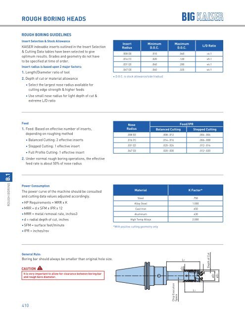
- Page 409: ROUGH BORING HEADS CC..16 (5/8" I.C
- Page 413 and 414: FINE BORING HEADS 414-450 FINE BORI
- Page 415 and 416: B.2 FINE BORING Download on the GET
- Page 417 and 418: FINE BORING HEADS EWN 2-152 FINE BO
- Page 419 and 420: FINE BORING HEADS ø4mm ø4mm 1.18
- Page 421 and 422: FINE BORING HEADS ADJUSTABLE TOOL H
- Page 423 and 424: FINE BORING HEADS 5.00 M6 ø11mm ø
- Page 425 and 426: FINE BORING HEADS BACK BORING CATAL
- Page 427 and 428: FINE BORING HEADS FACE GROOVING HOL
- Page 429 and 430: FINE BORING HEADS SERIES 112 BORING
- Page 431 and 432: FINE BORING HEADS EWN 2-32E FINE BO
- Page 433 and 434: FINE BORING HEADS ø4mm 1.18 .35 ø
- Page 435 and 436: FINE BORING HEADS ø9mm ø9mm 3.58
- Page 437 and 438: FINE BORING HEADS FIXED TOOL HOLDER
- Page 439 and 440: FINE BORING HEADS ø4mm ø4mm 1.18
- Page 441 and 442: FINE BORING HEADS .906 FIXED TOOL H
- Page 443 and 444: FINE BORING HEADS EWN 04-7E Fine Bo
- Page 445 and 446: FINE BORING HEADS 7 8 9 10 1 2 3 4
- Page 447 and 448: FINE BORING HEADS SERIES 112—INSE
- Page 449 and 450: FINE BORING HEADS SERIES 112 EWN 2-
- Page 451 and 452: 451 B.2 FINE BORING
- Page 453 and 454: FINE BORING HEADS 454-475 OVERVIEW
- Page 455 and 456: FINE BORING HEADS EWE DIGITAL FINE
- Page 457 and 458: FINE BORING HEADS EWN BIG CAPTO FIN
- Page 459 and 460: FINE BORING HEADS SMART DAMPER BORI
- Page 461 and 462:
FINE BORING HEADS SERIES 310—INSE
- Page 463 and 464:
FINE BORING HEADS SERIES 310—FACE
- Page 465 and 466:
FINE BORING HEADS SERIES 309 EWB-UP
- Page 467 and 468:
FINE BORING HEADS EWB-AL BALANCED F
- Page 469 and 470:
FINE BORING HEADS HYDRAULIC CHUCKS
- Page 471 and 472:
FINE BORING HEADS FINISH BORING TRO
- Page 473 and 474:
FINE BORING HEADS FINISH BORING INS
- Page 475 and 476:
FINE BORING HEADS SERIES 309 EWB-UP
- Page 477 and 478:
LARGE DIAMETER BORING HEADS 478-504
- Page 479 and 480:
LARGE DIAMETER BORING HEADS SERIES
- Page 481 and 482:
LARGE DIAMETER BORING HEADS ROUGH B
- Page 483 and 484:
LARGE DIAMETER BORING HEADS EWN/EWE
- Page 485 and 486:
LARGE DIAMETER BORING HEADS FINE BO
- Page 487 and 488:
LARGE DIAMETER BORING HEADS O.D. TU
- Page 489 and 490:
LARGE DIAMETER BORING TOOLS ROUGH A
- Page 491 and 492:
LARGE DIAMETER BORING HEADS Insert
- Page 493 and 494:
LARGE DIAMETER BORING TOOLS SAFETY
- Page 495 and 496:
LARGE DIAMETER BORING HEADS SERIES
- Page 497 and 498:
CHAMFER RINGS L1 L2 øB CKB Size
- Page 499 and 500:
SPECIAL TOOLS SPECIAL TOOL ACCESSOR
- Page 501 and 502:
ACCESSORIES FIXED SHELF MOUNT CARTR
- Page 503 and 504:
SPECIAL CK SHANKS NMTB—CKB SHANKS
- Page 505 and 506:
SPECIAL CK SHANKS B.4 LARGE DIAMETE
- Page 507 and 508:
INDEXABLE INSERTS 508-527 APPLICATI
- Page 509 and 510:
INDEXABLE INSERTS ISO CODE for Inse
- Page 511 and 512:
R INDEXABLE INSERTS INSERTS FOR FI
- Page 513 and 514:
INDEXABLE INSERTS INSERTS FOR FINE
- Page 515 and 516:
INDEXABLE INSERTS INSERTS FOR FINE
- Page 517 and 518:
80º INDEXABLE INSERTS INSERTS FOR
- Page 519 and 520:
80º INDEXABLE INSERTS INSERTS FOR
- Page 521 and 522:
INDEXABLE INSERTS CBN/PCD INSERTS F
- Page 523 and 524:
INDEXABLE INSERTS INSERTS FOR ROUGH
- Page 525 and 526:
INDEXABLE INSERTS CLAMP SCREWS & WR
- Page 527 and 528:
INDEXABLE INSERTS WRENCHES FOR INSE
- Page 529 and 530:
DRILLS 530-541 INDEXABLE INSERT DRI
- Page 531 and 532:
DRILLS SERIES 337 INSERT DRILL •
- Page 533 and 534:
DRILLS INDEXABLE INSERT DRILL—SER
- Page 535 and 536:
DRILLS INDEXABLE INSERT DRILL—SER
- Page 537 and 538:
DRILLS INDEXABLE INSERT DRILL—CUT
- Page 539 and 540:
DRILLS OFF-AXIS USE OF INDEXABLE IN
- Page 541 and 542:
DRILLS SPADE DRILL—APPLICATION GU
- Page 543 and 544:
INDEXABLE END MILLS FULLCUT MILL—
- Page 545 and 546:
INDEXABLE END MILLS FULLCUT MILL—
- Page 547 and 548:
INDEXABLE END MILLS FULLCUT MILL—
- Page 549 and 550:
INDEXABLE END MILLS CUTTING DATA FU
- Page 551 and 552:
INDEXABLE END MILLS FULLCUT MILL—
- Page 553 and 554:
INDEXABLE END MILLS FULLCUT MILL—
- Page 555 and 556:
INDEXABLE END MILLS FULLCUT MILL—
- Page 557 and 558:
INDEXABLE END MILLS FULLCUT MILL—
- Page 559 and 560:
INDEXABLE END MILLS FULLCUT MILL—
- Page 561 and 562:
EXCHANGEABLE HEAD MILLING TOOLS CON
- Page 563 and 564:
EXCHANGEABLE HEAD MILLING TOOLS CON
- Page 565 and 566:
EXCHANGEABLE HEAD MILLING TOOLS CON
- Page 567 and 568:
FACE MILLS Perpendicularity and Bea
- Page 569 and 570:
FACE MILLS SPEED FINISHER INSERTS .
- Page 571 and 572:
FACE MILLS SURFACE MILL INSERTS øD
- Page 573 and 574:
CHAMFER MILLS C-CUTTER MINI—SINGL
- Page 575 and 576:
CHAMFER MILLS C-CUTTER MINI—BOLT
- Page 577 and 578:
CHAMFER MILLS C-CUTTER MINI INSERTS
- Page 579 and 580:
CHAMFER MILLS C-CUTTER—CKB TYPE C
- Page 581 and 582:
CHAMFER MILLS C-CUTTER APPLICATION
- Page 583 and 584:
CHAMFER MILLS C-CENTERING CUTTER A
- Page 585 and 586:
CHAMFER MILLS C-CUTTER BOY Ideal fo
- Page 587 and 588:
RADIUS MILLS R-CUTTER—FRONT & BAC
- Page 589 and 590:
RADIUS MILLS R-CUTTER INSERTS Type
- Page 591 and 592:
BACK COUNTERBORING TOOLS BF-CUTTER
- Page 593 and 594:
GROOVE MILLING TOOLS BLANK INSERTS
- Page 595 and 596:
MEASURING INSTRUMENTS 596-614 POINT
- Page 597 and 598:
MEASURING INSTRUMENTS POINT MASTER
- Page 599 and 600:
MEASURING INSTRUMENTS POINT MASTER
- Page 601 and 602:
601 D.1 ACCESSORIES
- Page 603 and 604:
MEASURING INSTRUMENTS BASE MASTER R
- Page 605 and 606:
MEASURING INSTRUMENTS 3D MASTER RED
- Page 607 and 608:
MEASURING INSTRUMENTS DYNA FORCE Ma
- Page 609 and 610:
MEASURING INSTRUMENTS MEASUREMENT M
- Page 611 and 612:
MEASURING INSTRUMENTS LEVEL MASTER
- Page 613 and 614:
MEASURING INSTRUMENTS TYPE MU/FS
- Page 615 and 616:
TOOL ASSEMBLY DEVICES TOOL PRO The
- Page 617 and 618:
TOOL ASSEMBLY DEVICES TOOLING MATE
- Page 619 and 620:
TOOL ASSEMBLY DEVICES TORQUE FIT To
- Page 621 and 622:
CLEANERS SPINDLE CLEANERS The unbea
- Page 623 and 624:
CLEANERS T-SLOT CLEAN Improve your