


Create successful ePaper yourself
Turn your PDF publications into a flip-book with our unique Google optimized e-Paper software.
<strong>ICAM</strong> <strong>Virtual</strong> <strong>Machine</strong> ® Version 19.0 Creating <strong>Virtual</strong> <strong>Machine</strong> Models with Quest<br />
Adding Kinematics to the Model<br />
3.4 Adding Kinematics to the Model<br />
The machine kinematics must be constructed one axis at a time. Adding the kinematics framework<br />
first and then attaching the physical components to this framework afterwards is one<br />
suggested methodology. It is also possible to do the reverse, or to build the components and<br />
kinematics together.<br />
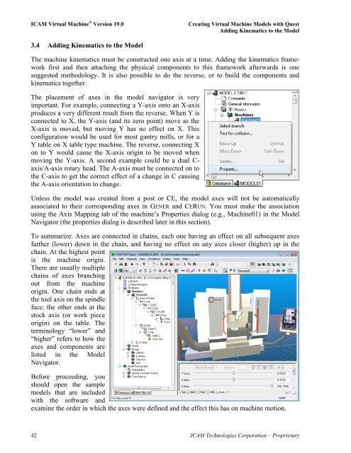
The placement of axes in the model navigator is very<br />
important. For example, connecting a Y-axis onto an X-axis<br />
produces a very different result from the reverse. When Y is<br />
connected to X, the Y-axis (and its zero point) move as the<br />
X-axis is moved, but moving Y has no effect on X. This<br />
configuration would be used for most gantry mills, or for a<br />
Y table on X table type machine. The reverse, connecting X<br />
on to Y would cause the X-axis origin to be moved when<br />
moving the Y-axis. A second example could be a dual Caxis/A-axis<br />
rotary head. The A-axis must be connected on to<br />
the C-axis to get the correct effect of a change in C causing<br />
the A-axis orientation to change.<br />
Unless the model was created from a post or CE, the model axes will not be automatically<br />
associated to their corresponding axes in GENER and CERUN. You must make the association<br />
using the Axis Mapping tab of the machine‟s Properties dialog (e.g., <strong>Machine</strong>01) in the Model<br />
Navigator (the properties dialog is described later in this section).<br />
To summarize: Axes are connected in chains, each one having an effect on all subsequent axes<br />
farther (lower) down in the chain, and having no effect on any axes closer (higher) up in the<br />
chain. At the highest point<br />
is the machine origin.<br />
There are usually multiple<br />
chains of axes branching<br />
out from the machine<br />
origin. One chain ends at<br />
the tool axis on the spindle<br />
face; the other ends at the<br />
stock axis (or work piece<br />
origin) on the table. The<br />
terminology “lower” and<br />
“higher” refers to how the<br />
axes and components are<br />
listed in the Model<br />
Navigator.<br />
Before proceeding, you<br />
should open the sample<br />
models that are included<br />
with the software and<br />
examine the order in which the axes were defined and the effect this has on machine motion.<br />
42 <strong>ICAM</strong> Technologies Corporation – Proprietary


