- Page 1:
Helmet-Mounted Displays: Design Iss
- Page 4 and 5:
The views, opinions, and/or finding
- Page 6 and 7:
vi Contents 4. Visual Coupling Clar
- Page 8 and 9:
viii Contents References ..........
- Page 10:
x Ben T. Mozo, Research Physicist U
- Page 13 and 14:
xii Foreword began its phenomenal e
- Page 15 and 16:
xiv Preface Acknowledgments The aut
- Page 18 and 19:
Introductory Overview 1 Clarence E.
- Page 20 and 21:
Introductory Overview 5 Figure 1.2.
- Page 22 and 23: Introductory Overview 7 The trend f
- Page 24 and 25: Introductory Overview 9
- Page 26 and 27: Introductory Overview 11 aviator to
- Page 28 and 29: Introductory Overview 13 1970's. Ta
- Page 30 and 31: Introductory Overview 15 Image sour
- Page 32 and 33: Introductory Overview 17
- Page 34 and 35: Table 1.3. HMD performance figures-
- Page 36 and 37: Introductory Overview 21 direct vie
- Page 38 and 39: Introductory Overview 23 Figure 1.9
- Page 40 and 41: Introductory Overview 25 Figure 1.1
- Page 42 and 43: Introductory Overview 27 Ercoline,
- Page 44 and 45: Introductory Overview 29 II, Procee
- Page 46: Introductory Overview 31 Armstrong
- Page 49 and 50: 34 Clarence E. Rash, Melissa H. Led
- Page 51 and 52: 36 Clarence E. Rash, Melissa H. Led
- Page 53 and 54: 38 Clarence E. Rash, Melissa H. Led
- Page 55 and 56: 40 Liquid crystal Clarence E. Rash,
- Page 57 and 58: 42 Clarence E. Rash, Melissa H. Led
- Page 59 and 60: 44 Clarence E. Rash, Melissa H. Led
- Page 61 and 62: 46 Clarence E. Rash, Melissa H. Led
- Page 63 and 64: 48 Clarence E. Rash, Melissa H. Led
- Page 65 and 66: 50 Clarence E. Rash, Melissa H. Led
- Page 67 and 68: 52 Clarence E. Rash, Melissa H. Led
- Page 70 and 71: Optical Designs 3 William E. McLean
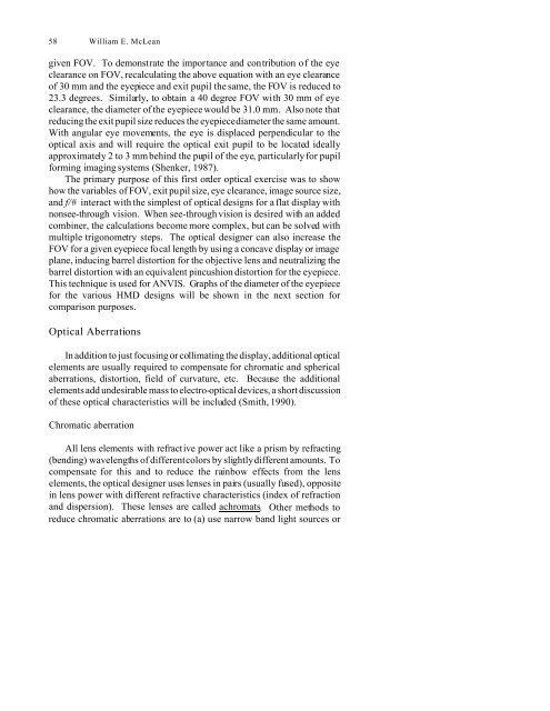
- Page 74 and 75: Optical Designs 59 phosphors, (b) u
- Page 76 and 77: Optical Designs 61 optics. Examples
- Page 78 and 79: Optical Designs 63
- Page 80 and 81: prism combiner. Optical Designs 65
- Page 82 and 83: Figure 3.2. (continued) Optical Des
- Page 84 and 85: Optical Designs 69
- Page 86 and 87: Optical Designs 71 Figure 3.4. Comp
- Page 88 and 89: Optical Designs 73 Figure 3.6. Opti
- Page 90 and 91: Optical Designs 75 Figure 3.8. Refl
- Page 92 and 93: Optical Designs 77 Figure 3.9. Ray
- Page 94 and 95: Optical Designs 79 incidence and re
- Page 96 and 97: 80 Clarence E. Rash hinted at befor
- Page 98 and 99: 82 Clarence E. Rash metal tolerant
- Page 100 and 101: 84 Clarence E. Rash the performance
- Page 102 and 103: 86 Clarence E. Rash Figure 4.3. Hig
- Page 104 and 105: 88 Clarence E. Rash imagery in HMDs
- Page 106 and 107: 90 Clarence E. Rash as with ANVIS.
- Page 108 and 109: 92 Clarence E. Rash performance, on
- Page 110 and 111: 94 Clarence E. Rash effects on visu
- Page 112 and 113: 96 Clarence E. Rash concerning roll
- Page 114 and 115: 98 Aeromedical Research Laboratory.
- Page 116: DESIGN ISSUES PART TWO
- Page 119 and 120: 102 Clarence E. Rash and William E.
- Page 121 and 122: 104 Contrast Clarence E. Rash and W
- Page 123 and 124:
106 Clarence E. Rash and William E.
- Page 125 and 126:
108 Clarence E. Rash and William E.
- Page 127 and 128:
110 Clarence E. Rash and William E.
- Page 129 and 130:
112 Clarence E. Rash and William E.
- Page 131 and 132:
114 Clarence E. Rash and William E.
- Page 133 and 134:
116 Clarence E. Rash and William E.
- Page 135 and 136:
118 Clarence E. Rash and William E.
- Page 137 and 138:
120 Clarence E. Rash and William E.
- Page 139 and 140:
122 Clarence E. Rash and William E.
- Page 141 and 142:
124 Clarence E. Rash and William E.
- Page 143 and 144:
126 Clarence E. Rash and William E.
- Page 145 and 146:
128 Clarence E. Rash and William E.
- Page 147 and 148:
130 Clarence E. Rash and William E.
- Page 149 and 150:
132 Clarence E. Rash and William E.
- Page 151 and 152:
134 Clarence E. Rash and William E.
- Page 153 and 154:
136 Clarence E. Rash and William E.
- Page 155 and 156:
138 Clarence E. Rash and William E.
- Page 157 and 158:
140 Clarence E. Rash and William E.
- Page 159 and 160:
142 Clarence E. Rash and William E.
- Page 161 and 162:
144 Clarence E. Rash and William E.
- Page 163 and 164:
146 Clarence E. Rash and William E.
- Page 165 and 166:
148 Clarence E. Rash and William E.
- Page 167 and 168:
150 Clarence E. Rash and William E.
- Page 169 and 170:
152 Clarence E. Rash and William E.
- Page 171 and 172:
154 Clarence E. Rash and William E.
- Page 173 and 174:
156 Clarence E. Rash and William E.
- Page 175 and 176:
158 Clarence E. Rash and William E.
- Page 177 and 178:
160 Clarence E. Rash and William E.
- Page 179 and 180:
162 Clarence E. Rash and William E.
- Page 181 and 182:
164 Clarence E. Rash and William E.
- Page 183 and 184:
166 Clarence E. Rash and William E.
- Page 185 and 186:
168 Number of SOG = � log (C r) /
- Page 187 and 188:
Visual Performance 6 William E. McL
- Page 189 and 190:
Visual Performance 171 observer is
- Page 191 and 192:
seen. Visual Performance 173 Figure
- Page 193 and 194:
Visual Performance 175 perception.
- Page 195 and 196:
Visual Performance 177 with monovis
- Page 197 and 198:
Visual Performance 179 individuals
- Page 199 and 200:
Visual Performance 181 0 to -5.25 d
- Page 201 and 202:
Visual Performance 183 Report No. 9
- Page 203 and 204:
Biodynamics 7 B. Joseph McEntire He
- Page 205 and 206:
Biodynamics 187 behavior of this de
- Page 207 and 208:
Figure 7.2. Head anatomical coordin
- Page 209 and 210:
Biodynamics 191
- Page 211 and 212:
Biodynamics 193 al., 1972), and man
- Page 213 and 214:
Biodynamics 195 Figure 7.5. Vertica
- Page 215 and 216:
Biodynamics 197 disability and fata
- Page 217 and 218:
Biodynamics 199 been fabricated int
- Page 219 and 220:
Biodynamics 201 Ty pic al acc ele r
- Page 221 and 222:
Biodynamics 203 exceed the mechanic
- Page 223 and 224:
Biodynamics 205 complexity and comp
- Page 225 and 226:
Type Reference helmet Foam in place
- Page 227 and 228:
Biodynamics 209 the fitting problem
- Page 229 and 230:
Biodynamics 211 adjustment buckle,
- Page 231 and 232:
Biodynamics 213 down. The helmet ma
- Page 233 and 234:
Biodynamics 215 Desert Shield/Deser
- Page 235 and 236:
Biodynamics 217 Donelson, S. M., an
- Page 237 and 238:
219 Fort Rucker, AL: U.S. Army Aero
- Page 239 and 240:
220 Ben T. Mozo Figure 8.1. Noise l
- Page 241 and 242:
222 Ben T. Mozo available in the ne
- Page 243 and 244:
224 Ben T. Mozo Protectors”(ANSI,
- Page 245 and 246:
226 Ben T. Mozo language. Tests of
- Page 247 and 248:
228 Ben T. Mozo Figure 8.6. Speech
- Page 249 and 250:
230 Ben T. Mozo the communications
- Page 251 and 252:
232 Ben T. Mozo Item Mass (grams) C
- Page 253 and 254:
Ribera, J. E., and Mozo, B. T. Unda
- Page 255 and 256:
236 Joseph R. Licina operational us
- Page 257 and 258:
238 Joseph R. Licina Standard MIL-S
- Page 259 and 260:
240 Joseph R. Licina On electro-opt
- Page 261 and 262:
242 Joseph R. Licina For HMDs with
- Page 263 and 264:
244 Joseph R. Licina 1994b) that wi
- Page 265 and 266:
246 Joseph R. Licina Table 9.2. Hea
- Page 267 and 268:
248 Joseph R. Licina provided a 93.
- Page 269 and 270:
250 Joseph R. Licina and buckles, a
- Page 271 and 272:
252 Joseph R. Licina authorized to
- Page 273 and 274:
254 Joseph R. Licina a nuclear flas
- Page 275 and 276:
256 Joseph R. Licina requirements:
- Page 277:
HMD PERFORMANCE ASSESSMENT PART THR
- Page 280 and 281:
262 Clarence E. Rash, John C. Mora,
- Page 282 and 283:
264 Clarence E. Rash, John C. Mora,
- Page 284 and 285:
266 Clarence E. Rash, John C. Mora,
- Page 286 and 287:
Glossary 11
- Page 288 and 289:
270 making stereoposis possible. Bi
- Page 290 and 291:
272 John C. Mora and M elissa H. Le
- Page 292 and 293:
274 John C. Mora and M elissa H. Le
- Page 294 and 295:
276 John C. Mora and M elissa H. Le
- Page 297 and 298:
NOTES ON CONTRIBUTORS Melissa H. Le
- Page 299:
Notes on Contributors 281 Research
- Page 303 and 304:
284 Index Breakaway force (see Fran
- Page 305 and 306:
286 Index movement, 55, 80, 84, 90,
- Page 307 and 308:
288 Index 198, 204, 205, 208, 210,
- Page 309 and 310:
290 Index Microphone, 15, 186, 224,
- Page 311 and 312:
292 Index Speech intelligibility (S


