Defensor Mk5 Technical Documentation
Defensor Mk5 Technical Documentation
Defensor Mk5 Technical Documentation

Create successful ePaper yourself
Turn your PDF publications into a flip-book with our unique Google optimized e-Paper software.
5.3 Steam installation<br />
5.3.1 Positioning and mounting of the steam distribution pipes<br />
The location for the steam distribution pipes should be determined at the time of dimensioning the air<br />
conditioning system. Please note the following instructions to ensure proper humidification of the duct<br />
air.<br />
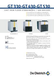
Calculating the humidification distance<br />
The water vapour, emitting from the steam distribution pipes, requires a certain distance to be absorbed<br />
by the ambient air so that it is no longer visible as steam. This distance is referred to as humidification<br />
distance “BN ” and serves as a basis for the determination of the minimum distances from the upstream<br />
components in the system.<br />
Humidification<br />
distance BN<br />
ϕ1 ϕ2<br />
1 x BN<br />
Expansion- and mixing zone<br />
ϕ1: Incoming air humidity before humidification<br />
ϕ2: Air humidity after humidification<br />
4-5 x BN<br />
The calculation of the humidification distance “B N ” is dependent on several factors. For a rough<br />
estimation of the humidification distance “B N ”, the following table is useful. Recommended standard<br />
values listed in this table are based on a supply-air temperature range of 15°C to 30°C. The values given<br />
in bold type only apply to steam distribution pipes 81-..., the values in brackets apply to the<br />
OptiSorp steam distribution system.<br />
Humidification distance BN in m<br />
Humidity at inlet Humidity at outlet<br />
ϕ1 in %rh ϕ2 in %rh<br />
40 50 60 70 80 90<br />
5 0.9 (0.22) 1.1 (0.28) 1.4 (0.36) 1.8 (0.48) 2.3 (0.66) 3.5 (1.08)<br />
10 0.8 (0.20) 1.0 (0.26) 1.3 (0.34) 1.7 (0.45) 2.2 (0.64) 3.4 (1.04)<br />
20 0.7 (0.16) 0.9 (0.22) 1.2 (0.30) 1.5 (0.41) 2.1 (0.58) 3.2 (0.96)<br />
30 0.5 (0.10) 0.8 (0.17) 1.0 (0.25) 1.4 (0.36) 1.9 (0.52) 2.9 (0.88)<br />
40 – 0.5 (0.11) 0.8 (0.20) 1.2 (0.30) 1.7 (0.45) 2.7 (0.79)<br />
50 – – 0.5 (0.13) 1.0 (0.24) 1.5 (0.38) 2.4 (0.69)<br />
60 – – – 0.7 (0.16) 1.2 (0.30) 2.1 (0.58)<br />
70 – – – – 0.8 (0.20) 1.7 (0.45)<br />
For duct widths