Defensor Mk5 Technical Documentation
Defensor Mk5 Technical Documentation
Defensor Mk5 Technical Documentation

You also want an ePaper? Increase the reach of your titles
YUMPU automatically turns print PDFs into web optimized ePapers that Google loves.
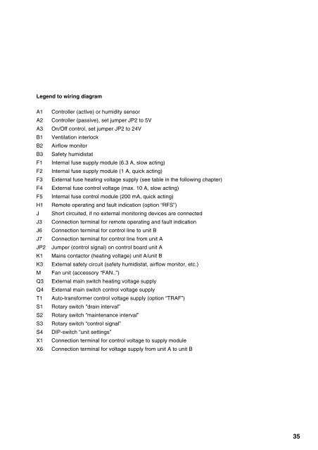
Legend to wiring diagram<br />
A1 Controller (active) or humidity sensor<br />
A2 Controller (passive), set jumper JP2 to 5V<br />
A3 On/Off control, set jumper JP2 to 24V<br />
B1 Ventilation interlock<br />
B2 Airflow monitor<br />
B3 Safety humidistat<br />
F1 Internal fuse supply module (6.3 A, slow acting)<br />
F2 Internal fuse supply module (1 A, quick acting)<br />
F3 External fuse heating voltage supply (see table in the following chapter)<br />
F4 External fuse control voltage (max. 10 A, slow acting)<br />
F5 Internal fuse control module (200 mA, quick acting)<br />
H1 Remote operating and fault indication (option “RFS”)<br />
J Short circuited, if no external monitoring devices are connected<br />
J3 Connection terminal for remote operating and fault indication<br />
J6 Connection terminal for control line to unit B<br />
J7 Connection terminal for control line from unit A<br />
JP2 Jumper (control signal) on control board unit A<br />
K1 Mains contactor (heating voltage) unit A/unit B<br />
K3 External safety circuit (safety humidistat, airflow monitor, etc.)<br />
M Fan unit (accessory “FAN..”)<br />
Q3 External main switch heating voltage supply<br />
Q4 External main switch control voltage supply<br />
T1 Auto-transformer control voltage supply (option “TRAF”)<br />
S1 Rotary switch "drain interval”<br />
S2 Rotary switch “maintenance interval”<br />
S3 Rotary switch “control signal”<br />
S4 DIP-switch “unit settings”<br />
X1 Connection terminal for control voltage to supply module<br />
X6 Connection terminal for voltage supply from unit A to unit B<br />
35