Workshopband als PDF - Mpc.belwue.de
Workshopband als PDF - Mpc.belwue.de
Workshopband als PDF - Mpc.belwue.de

Sie wollen auch ein ePaper? Erhöhen Sie die Reichweite Ihrer Titel.
YUMPU macht aus Druck-PDFs automatisch weboptimierte ePaper, die Google liebt.
MPC-WORKSHOP FEBRUAR 2013<br />
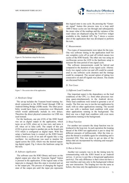
Figure 6: The hardware setup for the tests.<br />
Figure 7: The screen shot of the application.<br />
A. Hardware Setup<br />
The set-up inclu<strong>de</strong>s the Tsunami board running Android<br />
connected to the IOIO board through USB in<br />
Android Debug Bridge (ADB) mo<strong>de</strong>. The other possibility<br />
would have been a connection over Bluetooth<br />
which would additionally inclu<strong>de</strong> its own <strong>de</strong>lays.<br />
Therefore the direct physical connection via USB was<br />
used instead.<br />
For the hardware, one pin (#10) of the IOIO board<br />
was set as digital output in the application, which<br />
turns on an LED, when set to true (on), and turns it<br />
off, when set to f<strong>als</strong>e (off). The output of this pin<br />
(#10) is given as input to another pin on the board (pin<br />
#33) which is configured as digital input. With this<br />
setup a hardware loop is created on the IOIO board,<br />
which forms a cycle of on and off sign<strong>als</strong> like a ring<br />
oscillator. An oscilloscope was used to monitor the<br />
signal across the LED, which was the <strong>de</strong>sired repeating<br />
digital signal. Fig. 6 shows the hardware setup for<br />
the tests.<br />
B. Software Application<br />
The software uses the IOIO library and turns on the<br />
digital output pin when the "Generate Signal" button<br />
is pressed in the application. If the logical state of the<br />
input pin is changed, then this state is inverted and set<br />
to the output pin. The process of changing the logical<br />
state of the output pin until the input pin represents<br />
this logical state is one cycle. By pressing the “Generate<br />
signal” button this process runs in a loop until<br />
1000 if these cycles are run through and subsequently<br />
the mean value of the readings and the variance of the<br />
read values are displayed using the TextView widget<br />
available in the Android API. Fig. 7 shows a screen<br />
shot of the application that was <strong>de</strong>veloped to perform<br />
the tests.<br />
C. Measurements<br />
Two types of measurements were taken for the tests.<br />
One was software timing in the application itself for<br />
one complete cycle off on and off (which means two<br />
cycles of the IOIO board). The other one was using an<br />
oscilloscope across the LED in the hardware setup to<br />
measure the time period of one signal cycle.<br />
The software measurements could be halved and<br />
compared to the duration of one signal cycle. Alternatively<br />
two signal cycles (on and off) could be consi<strong>de</strong>red<br />
as one software cycle duration and the timings<br />
could be compared. The second option of taking two<br />
consecutive on and off sign<strong>als</strong> was chosen. The results<br />
are discussed below.<br />
D. Test Cases<br />
1) Different Load Conditions<br />
One important aspect is the <strong>de</strong>pen<strong>de</strong>ncy on the load<br />
conditions of the CPU, i.e. from other processes running<br />
quasi-simultaneously in the Android <strong>de</strong>vice.<br />
Three load conditions were tested to generate a set of<br />
results. The first one was to run the test application by<br />
itself, with no other applications running. The second<br />
one was with a medium load condition with some<br />
other applications running in the background. The<br />
third one was a high load condition with even more<br />
applications running in the background.<br />
2) Sleep Function<br />
For another test scenario the sleep function was introduced<br />
in the loop test. In each operation the looping<br />
thread of the IOIO test application is put to sleep for<br />
different amounts of milliseconds. After the time expires<br />
the thread is available again for scheduling and is<br />
executed [24]. This was done to get an i<strong>de</strong>a of the<br />
<strong>de</strong>lays that are incorporated by releasing and reacquiring<br />
the processor.<br />
3) Run as Service<br />
Another test scenario was to do the timing tests by<br />
communicating with the IOIO board in an Android<br />
service. A service is just like a foreground application<br />
(activity). The only difference is that it does not have a<br />
user interface and runs only in the background without<br />
any user interaction. The looping test was the same as<br />
before, this time only the application was run as a<br />
71
![[Geben Sie hier die Überschrift ein] - MPC](https://img.yumpu.com/8654082/1/188x260/geben-sie-hier-die-uberschrift-ein-mpc.jpg?quality=85)