
Create successful ePaper yourself
Turn your PDF publications into a flip-book with our unique Google optimized e-Paper software.
<strong>Technical</strong> <strong>Information</strong><br />
<strong>Technical</strong> <strong>Information</strong><br />
KM Manual Clamping System<br />
KM Manual Clamping Units<br />
KM Manual clamping units require a torque wrench to operate. Using the proper<br />
torque wrench value is critical. Tighter is not better because over tightening can<br />
cause damage.<br />
The specific operating torque of the KM manual clamping units is listed<br />
on each unit.<br />
The KM connection must be kept clean and free from nicks and burrs.<br />
KM plugs are available to ensure cleanliness when a cutting unit is not<br />
engaged in the clamping unit.<br />
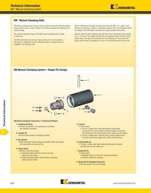
KM Manual Clamping System • Single-Pin Design<br />
8<br />
8<br />
KM Manual Clamping Components • Functional Definitions<br />
1. Clamping Unit Body<br />
• Primary component of the clamping unit assembly,<br />
less additional hardware.<br />
2. Canister Pin<br />
• Secures ball canister to clamping unit body.<br />
3. Pin Canister<br />
• Main component of KM clamping mechanism holds and locates<br />
the locking balls and bump-off pin.<br />
4. Torque Screw<br />
• Rotation moves the lockrod:<br />
a. Clockwise rotation advances lockrod, securing<br />
cutting unit (not shown).<br />
b. Counterclockwise rotation retracts lockrod, releasing<br />
cutting unit (not shown).<br />
7<br />
6<br />
6<br />
When a KM head is unlocked, the head will bump-off. KM’s 10:1 taper is selflocking,<br />
and therefore, requires a mechanical release. This is accomplished within<br />
the design of the KM System and does not require operator intervention.<br />
After the head has been released, you will need to turn the torque screw another<br />
3/4–1-1/2 turns. This rotation will feel free of resistance. When the free turning<br />
motion stops, the head can be pulled from the clamping unit. Do not turn the<br />
torque screw further, as damage can occur to the lockrod and/or bump-off pin.<br />
5<br />
3 4<br />
5. Lockrod<br />
• Dual function:<br />
a. Acts as a wedge when advanced between locking balls,<br />
causing them to move outward in the ball canister and pushing<br />
the locking balls into the ball tracks of the cutting unit (not shown).<br />
b. Acts as a wedge when retracted using a raised, tapered key to<br />
force the bump-off pin against the cutting unit (not shown).<br />
6. Locking Balls (2)<br />
• Precision, chrome alloy-steel hardened balls used to transmit<br />
pull-back force to the cutting unit.<br />
7. Bump-Off Pin<br />
• Dual function:<br />
a. Releases cutting unit from the clamping mechanism.<br />
b. Prevents lockrod from rotating.<br />
8. Bump-Off Pin Retention Screws (2)<br />
• Secures bump-off pin in ball canister.<br />
M22 www.kennametal.com<br />
2<br />
1