
Create successful ePaper yourself
Turn your PDF publications into a flip-book with our unique Google optimized e-Paper software.
<strong>Technical</strong> <strong>Information</strong><br />
<strong>Technical</strong> <strong>Information</strong><br />
KM Manual Clamping System<br />
KM Manual Clamping Unit • Assembly/Timing Procedures<br />
1. Place a small amount of GLEITMO 805 grease into the canister where the<br />
locking balls make contact, paying particular attention to the inner top surface<br />
of the locking ball bores.<br />
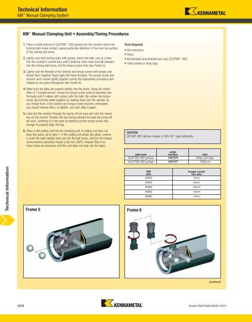
2. Lightly coat both locking balls with grease. Insert the balls, one at a time,<br />
into the canister’s central bore until it bottoms, then move the ball outward<br />
into the locking ball bores, not the torque screw hole (see Frame 5).<br />
3. Lightly coat the threads of the lockrod and torque screw with grease and<br />
thread them together finger tight (left-hand threads). The torque screw and<br />
lockrod must remain tightly together during the reassembly procedure and<br />
rotated as one piece throughout (see Frame 6).<br />
4. Make sure the balls are pushed radially into the bores. Using the metric<br />
Allen or T-handle wrench, thread the torque screw lockrod assembly into<br />
the body until it makes soft contact with the balls. Be certain the torque<br />
screw and lockrod rotate together by looking down into the canister as<br />
you thread them. If the lockrod and torque screw become unthreaded,<br />
you should remove them, re-tighten, and start Step 4 again.<br />
5. Look into the canister through the bump-off pin bore and note the raised<br />
key on the lockrod. Position the key facing outward through the bump-off<br />
pin bore, centering it in the bore by backing out the torque screw only<br />
enough to properly align the key.<br />
6. Place a KM cutting unit into the clamping unit. If cutting unit does not<br />
drop into place, go to Step 7. If the cutting unit drops into place, remove<br />
it, push the balls radially back out into the ball bores, and turn the torque<br />
screw/lockrod assembly inward a full turn (360°). Repeat Step 6 as<br />
many times as necessary until the unit does not drop into the taper.<br />
Frame 5 Frame 6<br />
Tools Required<br />
• Hex wrenches.<br />
• Pliers.<br />
• Kennametal recommends and uses GLEITMO 805.<br />
• Clean towels or shop rags.<br />
CAUTION<br />
DO NOT USE silicone cleaner or WD-40 -type lubricants.<br />
order<br />
lubricant<br />
number size<br />
GLEITMO 805 grease 1567575 500g cartridge<br />
GLEITMO 805 grease 1567577 1000g tin<br />
(continued)<br />
M28 www.kennametal.com<br />
KM<br />
size<br />
torque screw<br />
hex size<br />
KM32 5mm<br />
KM40 6mm<br />
KM50 10mm<br />
KM63 12mm<br />
KM80 14mm