
You also want an ePaper? Increase the reach of your titles
YUMPU automatically turns print PDFs into web optimized ePapers that Google loves.
Balancing (continued)<br />
The permissible residual unbalance can be calculated by the following equation:<br />
F = U x (n/9,549) 2 (Newtons)<br />
Where:<br />
In this particular case, the unbalanced induced force would be<br />
F = 1 x (25,000/9,549)2 = 6,9 N. The cutting forces generated<br />
are likely to be orders of magnitude greater than that.<br />
Unbalance can be corrected by material removal (drilling, milling, grinding),<br />
material addition (set screws), and material redistribution (balancing rings<br />
or set screws).<br />
Where:<br />
www.kennametal.com<br />
U = unbalance in gram millimeters (gmm)<br />
N = rotational speed (RPM)<br />
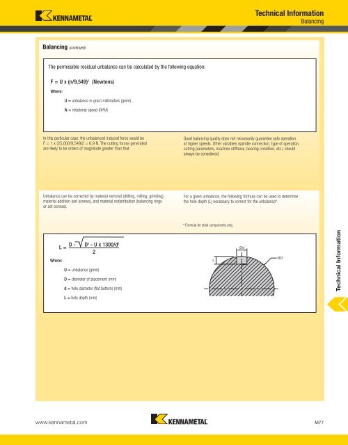
L = D - D2 - U x 1300/d 2<br />
2<br />
U = unbalance (gmm)<br />
D = diameter of placement (mm)<br />
d = hole diameter (flat bottom) (mm)<br />
L = hole depth (mm)<br />
<strong>Technical</strong> <strong>Information</strong><br />
Balancing<br />
Good balancing quality does not necessarily guarantee safe operation<br />
at higher speeds. Other variables (spindle connection, type of operation,<br />
cutting parameters, machine stiffness, bearing condition, etc.) should<br />
always be considered.<br />
For a given unbalance, the following formula can be used to determine<br />
the hole depth (L) necessary to correct for the unbalance*:<br />
* Formula for steel components only.<br />
M77<br />
<strong>Technical</strong> <strong>Information</strong>