
Create successful ePaper yourself
Turn your PDF publications into a flip-book with our unique Google optimized e-Paper software.
<strong>Technical</strong> <strong>Information</strong><br />
<strong>Technical</strong> <strong>Information</strong><br />
KM-LOC Clamping System<br />
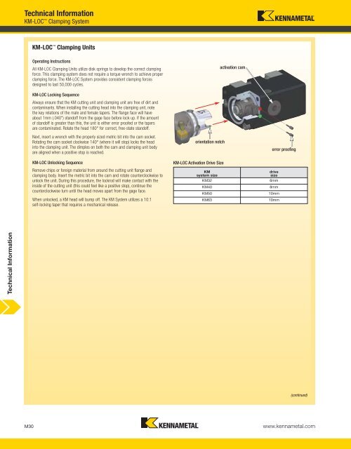
KM-LOC Clamping Units<br />
Operating Instructions<br />
All KM-LOC Clamping Units utilize disk springs to develop the correct clamping<br />
force. This clamping system does not require a torque wrench to achieve proper<br />
clamping force. The KM-LOC System provides consistent clamping forces<br />
designed to last 50,000 cycles.<br />
KM-LOC Locking Sequence<br />
Always ensure that the KM cutting unit and clamping unit are free of dirt and<br />
contaminants. When installing the cutting head into the clamping unit, note<br />
the key relations of the male and female tapers. The flange face will have<br />
about 1mm (.040") standoff from the gage face before lock up. If the amount<br />
of standoff is greater than this, the unit is either error proofed or the tapers<br />
are contaminated. Rotate the head 180° for correct, free-state standoff.<br />
Next, insert a wrench with the properly sized metric bit into the cam socket.<br />
Rotating the cam socket clockwise 140° (where it will stop) locks the head<br />
into the clamping unit. The dimples on both the cam and clamping unit body<br />
are aligned when a positive stop is reached.<br />
KM-LOC Unlocking Sequence<br />
Remove chips or foreign material from around the cutting unit flange and<br />
clamping body. Insert the metric bit into the cam and rotate counterclockwise to<br />
unlock the unit. During this procedure, the lockrod will make contact with the<br />
inside of the cutting unit (this could feel like a positive stop), continue the<br />
counterclockwise turn until the head moves apart from the gage face.<br />
When unlocked, a KM head will bump off. The KM System utilizes a 10:1<br />
self-locking taper that requires a mechanical release.<br />
orientation notch<br />
KM-LOC Activation Drive Size<br />
KM<br />
system size<br />
activation cam<br />
error proofing<br />
(continued)<br />
M30 www.kennametal.com<br />
drive<br />
size<br />
KM32 6mm<br />
KM40 8mm<br />
KM50 10mm<br />
KM63 10mm