
Create successful ePaper yourself
Turn your PDF publications into a flip-book with our unique Google optimized e-Paper software.
<strong>Technical</strong> <strong>Information</strong><br />
<strong>Technical</strong> <strong>Information</strong><br />
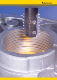
Tunable Boring Bars<br />
General Guidelines for Boring with Extended Reach Bars<br />
1. Select the largest boring bar diameter possible. Larger diameter bars<br />
are stiffer and more stable. Remember to leave enough space for<br />
chip evacuation.<br />
2. While larger diameters are more stable, the diameter may also be too large,<br />
preventing proper chip evacuation, affecting surface finish, or damaging<br />
the bar. Ensure the bar diameter is not so large that it will interfere with<br />
chip evacuation.<br />
3. Keep the overhang length of the tunable boring bar as short as possible.<br />
For Tunable Boring Bars, select the shortest bar possible.<br />
4. Balance machining parameters to prevent the occurrence of uncontrolled<br />
vibrations and resonance.<br />
5. The tool setting angle should be as close as possible to 90°.<br />
Selecting the Correct Bar<br />
Kennametal offers TTS Boring Bars with KM back-ends or straight shanks,<br />
KM front-ends, or bolt-on head connections, and they are available in<br />
either steel or carbide.<br />
To find the appropriate boring bar, first consider that the length-to-diameter ratio<br />
(L:D) should always be kept as small as possible. The smaller the L:D ratio, the<br />
greater the stiffness and stability of the bar.<br />
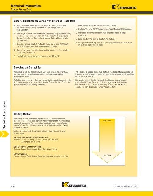
Holding Method<br />
The holding method is as critical to performance as selecting and tuning<br />
the boring bar. The connection between the boring bar and the machine should<br />
be as rigid as possible. Rigid connections enable the tuner mass to function<br />
more effectively. The minimum holding length of the bar should be 2.5x the<br />
diameter of the bar.<br />
Various connection methods are shown below and listed from most stable<br />
to least stable:<br />
Face and Taper Contact with Interference Fit<br />
Example: KM Tunable Boring Bar clamped with short overhang<br />
KM clamping unit on turret<br />
Split Sleeve/Full Cylindrical Contact<br />
Example: Straight Shank Tunable Boring Bar with split sleeve<br />
Screw Clamping<br />
Example: Straight Shank Tunable Boring Bar with screw clamping on bar flat<br />
6. Make sure the insert is in the correct center position.<br />
7. By choosing a small corner radius you can reduce forces on the workpiece.<br />
8. Use cutting heads with a negative back-rake angle that is as small<br />
as possible.<br />
9. Using inserts with a positive chip former is preferred.<br />
10. Change inserts when any flank wear is detected because radial back forces<br />
will increase in proportion to wear.<br />
The L:D ratios of Tunable Boring Bars are fixed, where straight shank tunable bar<br />
L:D ratios are not. When using straight shank bars, the overhang length should be<br />
kept as small as possible.<br />
Please note that only standard pretuned straight shank tunable bars are<br />
pretuned at the factory for 10:1 L:D. If the straight shank bar is mounted<br />
with less than 10:1 L:D, it may be necessary to retune the bar. This is<br />
discussed in more detail in the “Tuning the Bar” section.<br />
Most Stable<br />
Least Stable<br />
M94 www.kennametal.com