
You also want an ePaper? Increase the reach of your titles
YUMPU automatically turns print PDFs into web optimized ePapers that Google loves.
<strong>Technical</strong> <strong>Information</strong><br />
<strong>Technical</strong> <strong>Information</strong><br />
KM Application Data<br />
Operating Conditions<br />
The KM tooling joint is an extremely rigid and stable system that is specifically<br />
designed to supply consistent results. As with any mechanical coupling, KM has<br />
limits that, if exceeded, could result in mechanical damage to the joint and/or its<br />
components. To help you stay within these limits, Kennametal has established<br />
maximum safe tangential loads for each system size. These loads are described<br />
as a certain amount of force at the standard “F” and “L1” dimensions for each<br />
given system size.<br />
Example of Calculation:<br />
Where: P = rated tangential load<br />
K = empirical coefficient depending on<br />
KM system size and the units of measure<br />
P =<br />
KM32 K=190200<br />
KM40 K=383600<br />
KM50 K=887400<br />
KM63 K=1718000<br />
KM80 K=3085800<br />
K<br />
(0.8 L1) 2 + F 2<br />
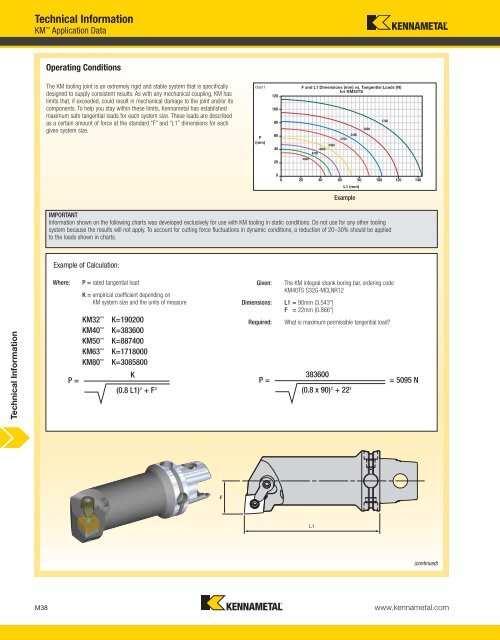
Chart 1 F and L1 Dimensions (mm) vs. Tangential Loads (N)<br />
for KM32TS<br />
120<br />
Given: The KM integral shank boring bar, ordering code<br />
KM40TS S32G-MCLNR12<br />
Dimensions: L1 = 90mm (3.543")<br />
F = 22mm (0.866")<br />
Required: What is maximum permissible tangential load?<br />
M38 www.kennametal.com<br />
F<br />
(mm)<br />
P =<br />
100<br />
80<br />
60<br />
40<br />
20<br />
4000<br />
4700<br />
5400<br />
0<br />
0 20 40 60 80 100 120 140<br />
383600<br />
L1 (mm)<br />
Example<br />
IMPORTANT<br />
<strong>Information</strong> shown on the following charts was developed exclusively for use with KM tooling in static conditions. Do not use for any other tooling<br />
system because the results will not apply. To account for cutting force fluctuations in dynamic conditions, a reduction of 20–30% should be applied<br />
to the loads shown in charts.<br />
3400<br />
2700<br />
(0.8 x 90) 2 + 22 2<br />
2400<br />
2000<br />
1700<br />
= 5095 N<br />
(continued)