
You also want an ePaper? Increase the reach of your titles
YUMPU automatically turns print PDFs into web optimized ePapers that Google loves.
<strong>Technical</strong> <strong>Information</strong><br />
<strong>Technical</strong> <strong>Information</strong><br />
KM Micro /KM Mini Manual Clamping System<br />
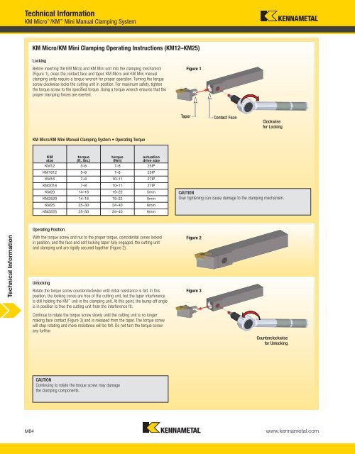
KM Micro/KM Mini Clamping Operating Instructions (KM12–KM25)<br />
Locking<br />
Before inserting the KM Micro and KM Mini unit into the clamping mechanism<br />
(Figure 1), clean the contact face and taper. KM Micro and KM Mini manual<br />
clamping units require a torque wrench for proper operation. Turning the torque<br />
screw clockwise locks the cutting unit in position. For maximum safety, tighten<br />
the torque screw to the specified torque. Using a torque wrench ensures that the<br />
proper clamping forces are exerted.<br />
KM Micro/KM Mini Manual Clamping System • Operating Torque<br />
KM<br />
size<br />
torque<br />
(ft. lbs.)<br />
torque<br />
(Nm)<br />
Operating Position<br />
With the torque screw and nut to the proper torque, coincidental cones locked<br />
in position, and the face and self-locking taper fully engaged, the cutting unit<br />
and clamping unit are rigidly secured together (Figure 2).<br />
Unlocking<br />
Rotate the torque screw counterclockwise until initial resistance is felt. In this<br />
position, the locking cones are free of the cutting unit, but the taper interference<br />
is still holding the KM unit in the clamping unit. At this point, the bump-off angle<br />
is in position to free the cutting unit from the interference fit.<br />
Continue to rotate the torque screw slowly until the cutting unit is no longer<br />
making face contact (Figure 3) and is released from the taper. The torque screw<br />
will stop rotating and more resistance will be felt. Do not turn the torque screw<br />
any further.<br />
CAUTION<br />
Continuing to rotate the torque screw may damage<br />
the clamping components.<br />
actuation<br />
drive size<br />
KM12 5–6 7–8 25IP<br />
KM1612 5–6 7–8 25IP<br />
KM16 7–8 10–11 27IP<br />
KM2016 7–8 10–11 27IP<br />
KM20 14–16 19–22 5mm<br />
KM2520 14–16 19–22 5mm<br />
KM25 25–30 34–40 6mm<br />
KM3225 25–30 34–40 6mm<br />
Figure 1<br />
Contact Face<br />
CAUTION<br />
Over tightening can cause damage to the clamping mechanism.<br />
Figure 2<br />
Figure 3<br />
M64 www.kennametal.com<br />
Taper<br />
Clockwise<br />
for Locking<br />
Counterclockwise<br />
for Unlocking