
You also want an ePaper? Increase the reach of your titles
YUMPU automatically turns print PDFs into web optimized ePapers that Google loves.
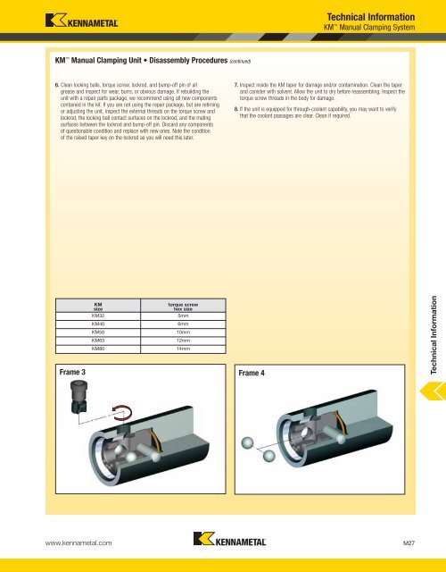
KM Manual Clamping Unit • Disassembly Procedures (continued)<br />
6. Clean locking balls, torque screw, lockrod, and bump-off pin of all<br />
grease and inspect for wear, burrs, or obvious damage. If rebuilding the<br />
unit with a repair parts package, we recommend using all new components<br />
contained in the kit. If you are not using the repair package, but are retiming<br />
or adjusting the unit, inspect the external threads on the torque screw and<br />
lockrod, the locking ball contact surfaces on the lockrod, and the mating<br />
surfaces between the lockrod and bump-off pin. Discard any components<br />
of questionable condition and replace with new ones. Note the condition<br />
of the raised taper key on the lockrod as you will need this later.<br />
www.kennametal.com<br />
<strong>Technical</strong> <strong>Information</strong><br />
KM Manual Clamping System<br />
7. Inspect inside the KM taper for damage and/or contamination. Clean the taper<br />
and canister with solvent. Allow the unit to dry before reassembling. Inspect the<br />
torque screw threads in the body for damage.<br />
8. If the unit is equipped for through-coolant capability, you may want to verify<br />
that the coolant passages are clear. Clean if required.<br />
KM<br />
torque screw<br />
size<br />
hex size<br />
KM32 5mm<br />
KM40 6mm<br />
KM50 10mm<br />
<strong>Information</strong><br />
KM63 12mm<br />
KM80 14mm<br />
Frame 3 Frame 4 <strong>Technical</strong><br />
M27