ECL Comfort 210/310, A217/A317 Installation Guide - Danfoss ...
ECL Comfort 210/310, A217/A317 Installation Guide - Danfoss ...
ECL Comfort 210/310, A217/A317 Installation Guide - Danfoss ...

You also want an ePaper? Increase the reach of your titles
YUMPU automatically turns print PDFs into web optimized ePapers that Google loves.
<strong>Installation</strong> <strong>Guide</strong> <strong>ECL</strong> <strong>Comfort</strong> <strong>210</strong> / <strong>310</strong>, application <strong>A217</strong> / <strong>A317</strong><br />
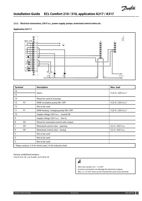
2.5.2 Electrical connections, 230 V a.c., power supply, pumps, motorized control valves etc.<br />
Application <strong>A217</strong>.1<br />
Terminal Description Max. load<br />
16<br />
15<br />
Alarm 4 (2) A / 230 V a.c.*<br />
14 Phase for control of pumps<br />
13 P3 DHW circulation pump ON / OFF 4 (2) A / 230 V a.c.*<br />
12 Not to be used<br />
11 P1 DHW heating / charging pump ON / OFF 4 (2) A / 230 V a.c.*<br />
10 Supply voltage 230 V a.c. - neutral (N)<br />
9 Supply voltage 230 V a.c. - live (L)<br />
8 M1 Phase for motorized control valve output<br />
7 M1 Motorized control valve - opening 0.2 A / 230 V a.c.<br />
6 M1 Motorized control valve - closing 0.2 A / 230 V a.c.<br />
5 Not to be used<br />
4 Not to be used<br />
3 Not to be used<br />
* Relay contacts: 4 A for ohmic load, 2 A for inductive load<br />
Factory established jumpers:<br />
5 to 8, 9 to 14, L to 5 and L to 9, N to 10<br />
Wire cross section: 0.5 - 1.5 mm²<br />
Incorrect connection can damage the electronic outputs.<br />
Max. 2 x 1.5 mm² wires can be inserted into each screw terminal.<br />
<strong>Danfoss</strong> District Energy VI.LG.U2.02 DEN-SMT/DK 27<br />
<strong>Danfoss</strong><br />
87H2082.10