ECL Comfort 210/310, A217/A317 Installation Guide - Danfoss ...
ECL Comfort 210/310, A217/A317 Installation Guide - Danfoss ...
ECL Comfort 210/310, A217/A317 Installation Guide - Danfoss ...

Create successful ePaper yourself
Turn your PDF publications into a flip-book with our unique Google optimized e-Paper software.
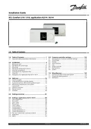
<strong>Installation</strong> <strong>Guide</strong> <strong>ECL</strong> <strong>Comfort</strong> <strong>210</strong> / <strong>310</strong>, application <strong>A217</strong> / <strong>A317</strong><br />
Xp actual<br />
Circuit Setting range Factory setting<br />
1 Read-out only<br />
‘Xp actual’ is the read-out of the actual Xp (proportional band) based on<br />
the supply temperature. Xp is determined by settings related to the supply<br />
temperature. Typically, the higher the supply temperature, the higher the Xp<br />
must be in order to achieve a stable temperature control.<br />
Xp setting range: 5 ... 250 K<br />
Fixed supply temperature settings: 65 °C and 90 °C<br />
Factory settings: (65,40) and (90,120)<br />
This means that the ‘Xp’ is 40 K at 65 °C supply temperature, and<br />
‘Xp’ is 120 K at 90 °C.<br />
Set the desired Xp values at the two fixed supply temperatures.<br />
If the supply temperature is not measured (the supply temperature<br />
sensor is not connected), the Xp value at the setting 65 °C is used.<br />
Tn (integration time constant) 11185<br />
Circuit Setting range Factory setting<br />
1 1 ... 999 s 30 s<br />
Set a high integration time constant (in seconds) to obtain a slow<br />
but stable reaction to deviations.<br />
A low integration time constant will make the controller react fast<br />
but with less stability.<br />
M run (running time of the motorized control valve) 11186<br />
Circuit Setting range Factory setting<br />
1 5 ... 250 s 30 s<br />
‘M run’ is the time in seconds it takes the controlled component<br />
to move from fully closed to fully open position. Set the ‘M run’<br />
according to the examples or measure the running time by means<br />
of a stop watch.<br />
Nz (neutral zone) 11187<br />
Circuit Setting range Factory setting<br />
1 1 ... 9 K 3 K<br />
Set the acceptable flow temperature deviation.<br />
Set the neutral zone to a high value if you can accept a high<br />
variation in flow temperature. When the actual flow temperature<br />
is within the neutral zone, the controller does not activate the<br />
motorized control valve.<br />
How to calculate the running time of a motorized control valve<br />
The running time of the motorized control valve is calculated using<br />
the following methods:<br />
Seated valves<br />
Running time = Valve stroke (mm) x actuator speed (sec. / mm)<br />
Example: 5.0 mm x 15 sec. / mm = 75 sec.<br />
Rotating valves<br />
Running time = Turning degrees x actuator speed (sec. / degr.)<br />
Example: 90 degr. x 2 sec. / degr. = 180 sec.<br />
The neutral zone is symmetrical around the desired flow temperature<br />
value, i.e. half the value is above and half the value is below this<br />
temperature.<br />
82 DEN-SMT/DK VI.LG.U2.02 <strong>Danfoss</strong> District Energy