ECL Comfort 210/310, A275/A375 Installation Guide - Danfoss ...
ECL Comfort 210/310, A275/A375 Installation Guide - Danfoss ...
ECL Comfort 210/310, A275/A375 Installation Guide - Danfoss ...

Create successful ePaper yourself
Turn your PDF publications into a flip-book with our unique Google optimized e-Paper software.
<strong>Installation</strong> <strong>Guide</strong> <strong>ECL</strong> <strong>Comfort</strong> <strong>210</strong> / <strong>310</strong>, application <strong>A275</strong> / <strong>A375</strong><br />
The application <strong>A375</strong>.1 is very flexible. These are the basic<br />
principles:<br />
The applications <strong>A375</strong>.1 / <strong>A375</strong>.2 / <strong>A375</strong>.3 can ON / OFF control up<br />
to 8 burner steps.<br />
In application <strong>A375</strong>.1 the first 4 burner steps are controlled by<br />
relays in the <strong>ECL</strong> <strong>310</strong>. The next, max. 4 burner steps, are controlled<br />
by relays in the extension module ECA 32 (placed in the base part<br />
of the <strong>ECL</strong> <strong>310</strong>).<br />
Heating (circuit 1):<br />
Typically, the common boiler temperature is adjusted according to<br />
your requirements. The boiler temperature sensor S3 is the most<br />
important sensor. It must be placed correctly in order to measure<br />
the common boiler temperature. The desired boiler temperature<br />
at S3 is calculated in the <strong>ECL</strong> controller, based on the outdoor<br />
temperature (S1). The lower the outdoor temperature, the higher<br />
the desired boiler temperature. The boiler temperature is also the<br />
flow temperature in the direct connected heating circuit.<br />
By means of a week schedule (up to 3 ‘<strong>Comfort</strong>’ periods / day), the<br />
heating circuit can be in ‘<strong>Comfort</strong>’ or ‘Saving’ mode (two different<br />
temperature values for the desired room temperature). In 'Saving'<br />
mode a 'Total stop' function can be selected in order to switch OFF<br />
the heating.<br />
The first burner step is switched ON when the common boiler<br />
temperature is lower than the desired boiler temperature. The<br />
controller observes the common boiler temperature and switches<br />
ON the next burner step if the common boiler temperature does<br />
not increase satisfactorily. The switching OFF procedure of burner<br />
steps is vice versa. A switching difference determines the ON / OFF<br />
control.<br />
The burners can be controlled in:<br />
• fixed sequence (example: Always 1-2-3-4-5) or<br />
• automatic rotating sequence (example: First period: 1-2-3-4-5,<br />
second period: 2-3-4-5-1, third period: 3-4-5-1-2 and so on)<br />
• semi-automatic rotating sequence (example: First period: 1,<br />
2-3-4-5, second period: 1, 3-4-5-2, third period: 1, 4-5-2-3 and<br />
so on)<br />
Furthermore, the boiler protection function will switch ON the<br />
circulation pump when the boiler temperature gets above a<br />
minimum value. A minimum ON-time can be set for the burner in<br />
order to increase the boiler's efficiency.<br />
The return temperature (S5) to the boiler should not be too<br />
high (condensing boiler) or too low (oil or gas fired boiler). If so,<br />
the desired boiler temperature can be decreased or increased.<br />
Furthermore, the return temperature limitation can be dependent<br />
of the outdoor temperature. Typically, the lower the outdoor<br />
temperature, the higher the accepted return temperature.<br />
If the measured room temperature (S7 or Remote control unit ECA<br />
30) does not equal the desired room temperature, the desired<br />
boiler temperature can be adjusted.<br />
The circulation pump (P1) is ON at heat demand or at frost<br />
protection.<br />
The heating can be switched OFF when the outdoor temperature is<br />
higher than a set value.<br />
The desired common boiler temperature can, via S10, be controlled<br />
by means of an external voltage in the range 0-10 volt.<br />
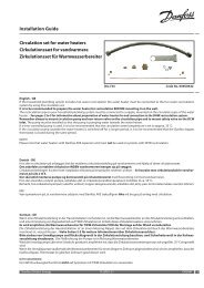
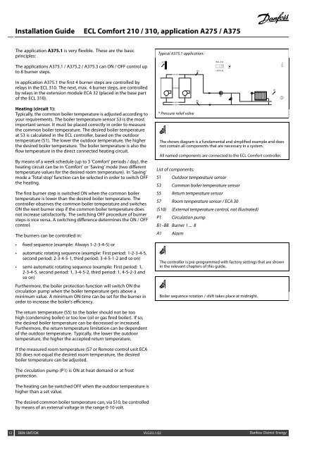
Typical <strong>A375</strong>.1 application:<br />
S1<br />
B1 B8<br />
* Pressure relief valve<br />
S3<br />
S5<br />
<strong>ECL</strong> <strong>310</strong><br />
+ ECA 32<br />
P1<br />
The shown diagram is a fundamental and simplified example and does<br />
not contain all components that are necessary in a system.<br />
All named components are connected to the <strong>ECL</strong> <strong>Comfort</strong> controller.<br />
List of components:<br />
S1 Outdoor temperature sensor<br />
S3 Common boiler temperature sensor<br />
S5 Return temperature sensor<br />
S7 Room temperature sensor / ECA 30<br />
(S10) (External temperature control, not illustrated)<br />
P1 Circulation pump<br />
B1–B8 Burner 1 ... 8<br />
A1 Alarm<br />
The controller is pre-programmed with factory settings that are shown<br />
in the relevant chapters of this guide.<br />
Boiler sequence rotation / shift takes place at midnight.<br />
12 DEN-SMT/DK VI.GU.L1.02 <strong>Danfoss</strong> District Energy<br />
A1<br />
*<br />
S7<br />
①<br />
<strong>Danfoss</strong><br />
87H2182.10