ECL Comfort 210/310, A275/A375 Installation Guide - Danfoss ...
ECL Comfort 210/310, A275/A375 Installation Guide - Danfoss ...
ECL Comfort 210/310, A275/A375 Installation Guide - Danfoss ...

You also want an ePaper? Increase the reach of your titles
YUMPU automatically turns print PDFs into web optimized ePapers that Google loves.
<strong>Installation</strong> <strong>Guide</strong> <strong>ECL</strong> <strong>Comfort</strong> <strong>210</strong> / <strong>310</strong>, application <strong>A275</strong> / <strong>A375</strong><br />
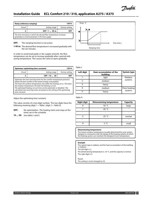
Ramp (reference ramping) 12013<br />
Circuit Setting range Factory setting<br />
2 OFF / 1 ... 99 m OFF<br />
The time (minutes) in which the desired flow temperature increases<br />
gradually to avoid load peaks in the heat supply.<br />
OFF: The ramping function is not active.<br />
1-99 m: The desired flow temperature is increased gradually with<br />
the set minutes.<br />
In order to avoid load peaks in the supply network, the flow<br />
temperature can be set to increase gradually after a period with<br />
saving temperature. This causes the valve to open gradually.<br />
Optimizer (optimizing time constant) 12014<br />
Circuit Setting range Factory setting<br />
2 OFF / 10 ... 59 OFF<br />
Optimizes the start and stop times for the comfort temperature period to<br />
obtain the best comfort at the lowest energy consumption.<br />
The lower the outdoor temperature, the earlier the heating cut-in. The lower<br />
the outdoor temperature, the later the heating cut-out.<br />
The optimized heating cut-out time can be automatic or disabled. The<br />
calculated start and stop times are based on the setting of the optimizing<br />
time constant.<br />
Adjust the optimizing time constant.<br />
The value consists of a two digit number. The two digits have the<br />
following meaning (digit 1 = Table I, digit 2 = Table II).<br />
OFF: No optimization. The heating starts and stops at the<br />
times set in the schedule.<br />
10 ... 59: See tables I and II.<br />
Table I:<br />
Temp. °C<br />
Ramping time<br />
Time (min.)<br />
Left digit Heat accumulation of the<br />
building<br />
1- light<br />
Table II:<br />
2- medium<br />
3- heavy<br />
4- medium<br />
5- heavy<br />
System type<br />
Radiator<br />
systems<br />
Floor heating<br />
systems<br />
Right digit Dimensioning temperature Capacity<br />
-0 -50 °C large<br />
-1 -45 °C ·<br />
· · ·<br />
-5 -25 °C normal<br />
· · ·<br />
-9 -5 °C small<br />
Dimensioning temperature:<br />
The lowest outdoor temperature (usually determined by your system<br />
designer in connection with the design of the heating system) at which<br />
the heating system can maintain the designed room temperature.<br />
Example<br />
The system type is radiator, and the heat accumulation of the building<br />
is medium.<br />
The left digit is 2.<br />
The dimensioning temperature is -25 °C, and the capacity is normal.<br />
The right digit is 5.<br />
Result:<br />
The setting is to be changed to 25.<br />
<strong>Danfoss</strong> District Energy VI.GU.L1.02 DEN-SMT/DK 133