INSTRUCTION MANUAL - Scorpio
INSTRUCTION MANUAL - Scorpio
INSTRUCTION MANUAL - Scorpio

Create successful ePaper yourself
Turn your PDF publications into a flip-book with our unique Google optimized e-Paper software.
RADIO INSTALLATION<br />
Follow these guidelines to properly mount the servos, receiver and battery.<br />
alignment tab on the battery, switch and servo connectors is oriented correctly and “keys”<br />
into the corresponding notch in the receiver or connectors before plugging them in. When unplugging<br />
connectors, never pull on the wires. Always pull on the plastic connector instead.<br />
<br />
to extend the length of the servo lead. Additional Futaba extension cords of varying lengths are available<br />
from your hobby dealer. Always use an extension of the proper length. Avoid plugging multiple extensions<br />
together to attain your desired length. If distance is greater than 18” or multiple or high current draw servos<br />
are being used, use Futaba Heavy-Duty servo extensions.<br />
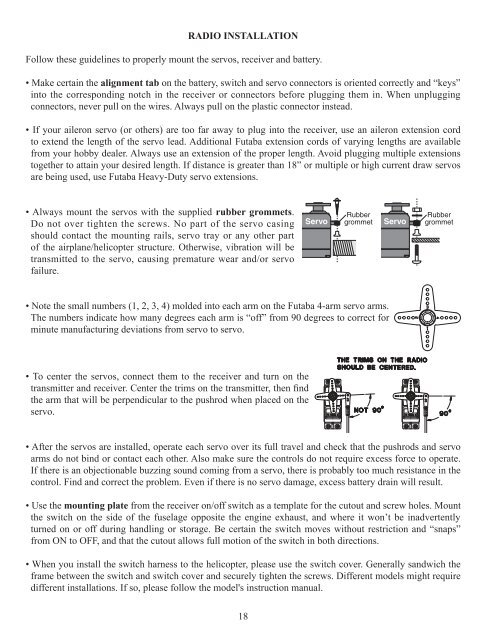
rubber grommets.<br />
Do not over tighten the screws. No part of the servo casing<br />
should contact the mounting rails, servo tray or any other part<br />
of the airplane/helicopter structure. Otherwise, vibration will be<br />
transmitted to the servo, causing premature wear and/or servo<br />
failure.<br />
18<br />
Servo<br />
Rubber<br />
grommet Servo<br />
<br />
The numbers indicate how many degrees each arm is “off” from 90 degrees to correct for<br />
minute manufacturing deviations from servo to servo.<br />
<br />
<br />
the arm that will be perpendicular to the pushrod when placed on the<br />
servo.<br />
Rubber<br />
grommet<br />
<br />
arms do not bind or contact each other. Also make sure the controls do not require excess force to operate.<br />
If there is an objectionable buzzing sound coming from a servo, there is probably too much resistance in the<br />
control. Find and correct the problem. Even if there is no servo damage, excess battery drain will result.<br />
mounting plate from the receiver on/off switch as a template for the cutout and screw holes. Mount<br />
the switch on the side of the fuselage opposite the engine exhaust, and where it won’t be inadvertently<br />
turned on or off during handling or storage. Be certain the switch moves without restriction and “snaps”<br />
from ON to OFF, and that the cutout allows full motion of the switch in both directions.<br />
<br />
frame between the switch and switch cover and securely tighten the screws. Different models might require<br />
different installations. If so, please follow the model's instruction manual.