- Page 1 and 2: s SIMATIC Statement List (STL) for
- Page 3 and 4: Preface Purpose This manual is your
- Page 5 and 6: Preface Online Help The manual is c
- Page 7 and 8: Contents 1 Bit Logic Instructions 1
- Page 9 and 10: Contents 8 Floating-Point Math Inst
- Page 11: Contents 14 Accumulator Instruction
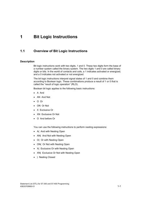
- Page 15 and 16: 1.2 A And Format A Address Data ty
- Page 17 and 18: 1.4 O Or Format O Address Data typ
- Page 19 and 20: 1.6 X Exclusive Or Format X Addres
- Page 21 and 22: 1.8 O And before Or Format Descript
- Page 23 and 24: 1.10 AN( And Not with Nesting Open
- Page 25 and 26: 1.14 XN( Exclusive Or Not with Nest
- Page 27 and 28: Example Statement List Program A( O
- Page 29 and 30: 1.17 R Reset Format R Address Data
- Page 31 and 32: 1.19 NOT Negate RLO Format Descript
- Page 33 and 34: 1.21 CLR Clear RLO (=0) Format Desc
- Page 35 and 36: 1.23 FN Edge Negative Format FN Bi
- Page 37 and 38: 1.24 FP Edge Positive Format FP Bi
- Page 39 and 40: 2 Comparison Instructions 2.1 Overv
- Page 41 and 42: 2.3 ? D Compare Double Integer (32-
- Page 43 and 44: 3 Conversion Instructions 3.1 Overv
- Page 45 and 46: 3.3 ITB Integer (16-Bit) to BCD For
- Page 47 and 48: 3.5 ITD Integer (16 Bit) to Double
- Page 49 and 50: Conversion Instructions 3.7 DTR Dou
- Page 51 and 52: Conversion Instructions 3.9 INVD On
- Page 53 and 54: Conversion Instructions 3.11 NEGD T
- Page 55 and 56: Conversion Instructions 3.13 CAW Ch
- Page 57 and 58: 3.15 RND Round Format Description S
- Page 59 and 60: 3.17 RND+ Round to Upper Double Int
- Page 61 and 62: 4 Counter Instructions 4.1 Overview
- Page 63 and 64:
4.3 L Load Current Counter Value in
- Page 65 and 66:
4.5 R Reset Counter Format Descript
- Page 67 and 68:
4.7 CU Counter Up Format CU Counte
- Page 69 and 70:
5 Data Block Instructions 5.1 Overv
- Page 71 and 72:
5.3 CDB Exchange Shared DB and Inst
- Page 73 and 74:
Data Block Instructions 5.6 L DILG
- Page 75 and 76:
6 Logic Control Instructions 6.1 Ov
- Page 77 and 78:
6.2 JU Jump Unconditional Format De
- Page 79 and 80:
6.4 JC Jump if RLO = 1 Format Descr
- Page 81 and 82:
6.6 JCB Jump if RLO = 1 with BR For
- Page 83 and 84:
6.8 JBI Jump if BR = 1 Format Descr
- Page 85 and 86:
6.10 JO Jump if OV = 1 Format Descr
- Page 87 and 88:
6.12 JZ Jump if Zero Format Descrip
- Page 89 and 90:
6.14 JP Jump if Plus Format Descrip
- Page 91 and 92:
6.16 JPZ Jump if Plus or Zero Forma
- Page 93 and 94:
6.18 JUO Jump if Unordered Format D
- Page 95 and 96:
7 Integer Math Instructions 7.1 Ove
- Page 97 and 98:
Integer Math Instructions 7.3 +I Ad
- Page 99 and 100:
Integer Math Instructions 7.5 *I Mu
- Page 101 and 102:
Example: 13 divided by 4 Contents o
- Page 103 and 104:
Example 3 STL Explanation L MD20 L
- Page 105 and 106:
Integer Math Instructions 7.9 -D Su
- Page 107 and 108:
Integer Math Instructions 7.11 /D D
- Page 109 and 110:
Integer Math Instructions 7.12 MOD
- Page 111 and 112:
8 Floating-Point Math Instructions
- Page 113 and 114:
8.3 Floating-Point Math Instruction
- Page 115 and 116:
Floating-Point Math Instructions 8.
- Page 117 and 118:
Floating-Point Math Instructions 8.
- Page 119 and 120:
Floating-Point Math Instructions 8.
- Page 121 and 122:
Floating-Point Math Instructions 8.
- Page 123 and 124:
Floating-Point Math Instructions 8.
- Page 125 and 126:
Floating-Point Math Instructions 8.
- Page 127 and 128:
Floating-Point Math Instructions 8.
- Page 129 and 130:
Floating-Point Math Instructions 8.
- Page 131 and 132:
9 Load and Transfer Instructions 9.
- Page 133 and 134:
Contents of ACCU 1 Load and Transfe
- Page 135 and 136:
Load and Transfer Instructions 9.4
- Page 137 and 138:
Load and Transfer Instructions 9.6
- Page 139 and 140:
9.9 T Transfer Format Description S
- Page 141 and 142:
Load and Transfer Instructions 9.11
- Page 143 and 144:
Load and Transfer Instructions 9.14
- Page 145 and 146:
10 Program Control Instructions 10.
- Page 147 and 148:
10.3 BEC Block End Conditional Form
- Page 149 and 150:
10.5 CALL Block Call Format Descrip
- Page 151 and 152:
10.6 Call FB Format Description CAL
- Page 153 and 154:
10.7 Call FC Format Description CAL
- Page 155 and 156:
10.8 Call SFB Format Description CA
- Page 157 and 158:
10.9 Call SFC Format Description CA
- Page 159 and 160:
10.12 CC Conditional Call Format De
- Page 161 and 162:
10.14 MCR (Master Control Relay) !
- Page 163 and 164:
10.15 Important Notes on Using MCR
- Page 165 and 166:
Example Program Control Instruction
- Page 167 and 168:
10.18 MCRA Activate MCR Area Format
- Page 169 and 170:
11 Shift and Rotate Instructions 11
- Page 171 and 172:
Example 1 STL Explanation L MW4 //L
- Page 173 and 174:
Examples Shift and Rotate Instructi
- Page 175 and 176:
Examples Shift and Rotate Instructi
- Page 177 and 178:
Examples Shift and Rotate Instructi
- Page 179 and 180:
Examples Shift and Rotate Instructi
- Page 181 and 182:
Examples Shift and Rotate Instructi
- Page 183 and 184:
11.2.2 RLD Rotate Left Double Word
- Page 185 and 186:
11.2.3 RRD Rotate Right Double Word
- Page 187 and 188:
11.2.4 RLDA Rotate ACCU 1 Left via
- Page 189 and 190:
12 Timer Instructions 12.1 Overview
- Page 191 and 192:
Time Base Timer Instructions Bits 1
- Page 193 and 194:
12.3 FR Enable Timer (Free) Format
- Page 195 and 196:
Timer Instructions 12.4 L Load Curr
- Page 197 and 198:
Timer Instructions 12.5 LC Load Cur
- Page 199 and 200:
12.6 R Reset Timer Format R Timer
- Page 201 and 202:
Enable input Start input Reset inpu
- Page 203 and 204:
Enable input Start input Reset inpu
- Page 205 and 206:
Enable Input Start Input Reset Inpu
- Page 207 and 208:
Enable input Start input Reset inpu
- Page 209 and 210:
Enable input Start input Reset inpu
- Page 211 and 212:
13 Word Logic Instructions 13.1 Ove
- Page 213 and 214:
Examples Word Logic Instructions Bi
- Page 215 and 216:
Examples Word Logic Instructions Bi
- Page 217 and 218:
Examples Word Logic Instructions Bi
- Page 219 and 220:
Examples Word Logic Instructions Bi
- Page 221 and 222:
Examples Word Logic Instructions Bi
- Page 223 and 224:
Examples Word Logic Instructions Bi
- Page 225 and 226:
14 Accumulator Instructions 14.1 Ov
- Page 227 and 228:
14.3 POP CPU with Two ACCUs Format
- Page 229 and 230:
14.5 PUSH CPU with Two ACCUs Format
- Page 231 and 232:
14.7 ENT Enter ACCU Stack Format De
- Page 233 and 234:
14.10 DEC Decrement ACCU 1-L-L Form
- Page 235 and 236:
14.12 +AR2 Add ACCU 1 to Address Re
- Page 237 and 238:
14.15 NOP 1 Null Instruction Format
- Page 239 and 240:
A Overview of All STL Instructions
- Page 241 and 242:
German Mnemonics English Mnemonics
- Page 243 and 244:
German Mnemonics English Mnemonics
- Page 245 and 246:
Overview of All STL Instructions A.
- Page 247 and 248:
English Mnemonics German Mnemonics
- Page 249 and 250:
English Mnemonics German Mnemonics
- Page 251 and 252:
B Programming Examples B.1 Overview
- Page 253 and 254:
Absolute and symbolic Programming P
- Page 255 and 256:
Absolute and symbolic Programming P
- Page 257 and 258:
B.3 Example: Timer Instructions Clo
- Page 259 and 260:
Signal states of the Bits of Memory
- Page 261 and 262:
Statement List that Activates the I
- Page 263 and 264:
B.6 Example: Word Logic Instruction
- Page 265 and 266:
C Parameter Transfer ! The paramete
- Page 267 and 268:
Index ) ) .........................
- Page 269 and 270:
I -I ..............................
- Page 271 and 272:
SLD................................


