WM, Workshop Manual, K650, K700, K950, K1250, 2001-06, Power ...
WM, Workshop Manual, K650, K700, K950, K1250, 2001-06, Power ...
WM, Workshop Manual, K650, K700, K950, K1250, 2001-06, Power ...

You also want an ePaper? Increase the reach of your titles
YUMPU automatically turns print PDFs into web optimized ePapers that Google loves.
2<br />
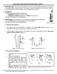
Ignition system<br />
The engine is fitted with an electronic ignition system<br />
consisting of flywheel, ignition coil and trigger<br />
unit.<br />
The ignition system has no moving parts. A defective<br />
component cannot be repaired but must be replaced<br />
with a new one.<br />
The ignition spark in an electronic ignition system<br />
has a very short burn time and may therefore be<br />
experienced as weak, and sometimes be dif ficult to<br />
see during trouble shooting.<br />
NOTE!<br />
During all test running of the cutting saw the<br />
clutch and clutch cover must be fitted before the<br />
engine is started!<br />
C<br />
N<br />
3<br />
B<br />
B<br />
2<br />
S<br />
N<br />
A<br />
1<br />
S<br />
+<br />
0<br />
-<br />
Volts<br />
1<br />
D<br />
2<br />
G<br />
E<br />
3<br />
F<br />
E = Ignition point<br />
F = Trigger unit<br />
G = Stop switch<br />
Principle of the ignition<br />
system<br />
The ignition system is completely enclosed<br />
and no after-adjustment of the<br />
ignition point is possible or necessary.<br />
The ignition module is built up of an iron<br />
core (C). Round this lies the primary coil<br />
(A) which consists of a small number of<br />
turns of thick copper wire. Outside this<br />
lies the secondary coil (B) which has a<br />
very large number of turns of copper<br />
wire.<br />
The trigger unit (F) is fitted on the<br />
secondary coil and has the purpose of<br />
breaking the current (D) in the primary<br />
winding at exactly the right time, i.e. just<br />
before the piston reaches the top dead<br />
centre.<br />
When the permanent magnet (1) on the<br />
flywheel passes the ignition module’s<br />
iron core, an electric current is generated<br />
in the primary coil (A). At the breaking<br />
moment the current in the primary coil<br />
rises from 5 volts to approx. 200 volts by<br />
means of induction.<br />
In the secondary coil (B) a high voltage<br />
(approx. 20 000 volts) is simultaneously<br />
transformed to the spark plug.<br />
Models <strong>K650</strong>,<strong>K700</strong>, <strong>K950</strong> and <strong>K1250</strong><br />
have a built-in overspeeding protection<br />
in the electronic unit which limits the<br />
unloaded speed of the engine to about<br />
9 750 rpm.<br />
C<br />
A<br />
The ignition module components are<br />
completely enclosed to protect them from<br />
moisture and dirt.<br />
In the event of a failure in the ignition<br />
module it must be replaced with a new<br />
one.<br />
The ignition module components are<br />
completely enclosed to protect them from<br />
moisture and dirt.<br />
In the event of a failure in the ignition<br />
module it must be replaced with a new<br />
one.<br />
F<br />
A = Primary coil<br />
B = Secondary coil<br />
C = Iron core<br />
F = Trigger unit<br />
12