WM, Workshop Manual, K650, K700, K950, K1250, 2001-06, Power ...
WM, Workshop Manual, K650, K700, K950, K1250, 2001-06, Power ...
WM, Workshop Manual, K650, K700, K950, K1250, 2001-06, Power ...

Create successful ePaper yourself
Turn your PDF publications into a flip-book with our unique Google optimized e-Paper software.
10<br />
5<br />
50<br />
Fuel system<br />
3<br />
Combinations of carburettors, induction pipe, seals, screwdriver guides<br />
<strong>K650</strong> Active, <strong>K700</strong> Active<br />
Carburettor Induct. pipe Seal Insert, seal Screwdriver guide<br />
HS175E 503 28 03-20 5<strong>06</strong> 21 41-01 5<strong>06</strong> 22 65-01 Black<br />
Not compensated Black Rubber foam, bonded to cyl. housing<br />
<strong>K650</strong> Active II, <strong>K700</strong> Active II<br />
Carburettor Induct. pipe Seal Insert, seal Screwdriver guide<br />
HS175F 503 28 04-03 5<strong>06</strong> 21 41-01 5<strong>06</strong> 25 34-01 5<strong>06</strong> 25 33-01 Blue<br />
Compensated, blue insert Black Moulded Blue<br />
HS175G 503 28 04-04 5<strong>06</strong> 21 41-01 5<strong>06</strong> 25 34-01 5<strong>06</strong> 25 33-01 Blue<br />
Compensated,blue insert Black Moulded Blue<br />
Small needle valve<br />
HS175G 503 28 04-08 5<strong>06</strong> 26 72-01 5<strong>06</strong> 26 85-01 –<br />
Comp., green insert, EPA Blue Moulded<br />
HS175L 503 28 04-15 5<strong>06</strong> 31 16-01 5<strong>06</strong> 26 85-01 –<br />
Comp., yellow insert, EPA Yellow Moulded<br />
Tower model<br />
HS175L, 503 28 04-16 5<strong>06</strong> 31 16-01 5<strong>06</strong> 26 85-01 Grey<br />
Comp., grey insert, EPA Grey Moulded<br />
Tower model<br />
There are different sizes and versions of carburettors on the different models, but in<br />
terms of servicing they are all treated in the same way.<br />
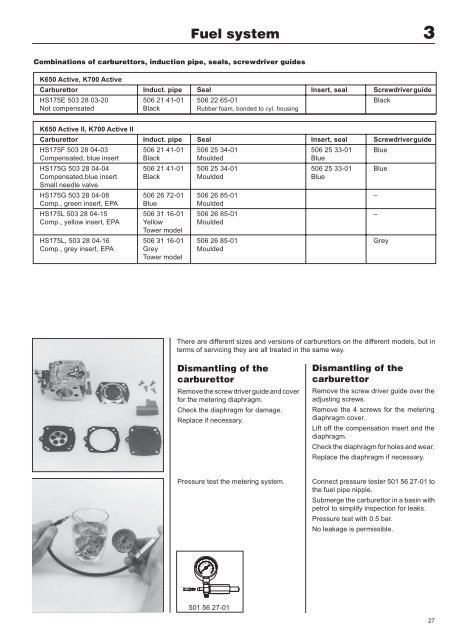
Dismantling of the<br />
carburettor<br />
Remove the screw driver guide and cover<br />
for the metering diaphragm.<br />
Check the diaphragm for damage.<br />
Replace if necessary.<br />
Dismantling of the<br />
carburettor<br />
Remove the screw driver guide over the<br />
adjusting screws.<br />
Remove the 4 screws for the metering<br />
diaphragm cover.<br />
Lift off the compensation insert and the<br />
diaphragm.<br />
Check the diaphragm for holes and wear.<br />
Replace the diaphragm if necessary.<br />
Pressure test the metering system.<br />
Connect pressure tester 501 56 27-01 to<br />
the fuel pipe nipple.<br />
Submerge the carburettor in a basin with<br />
petrol to simplify inspection for leaks.<br />
Pressure test with 0.5 bar.<br />
No leakage is permissible.<br />
30<br />
200<br />
150<br />
250<br />
15<br />
100<br />
300<br />
350<br />
50<br />
400<br />
0<br />
20<br />
0<br />
25<br />
35<br />
40<br />
60<br />
45<br />
55<br />
501 56 27-01<br />
27