

SG4E Full Rev01.pdf - Datasensor
SG4E Full Rev01.pdf - Datasensor
SG4E Full Rev01.pdf - Datasensor

Create successful ePaper yourself
Turn your PDF publications into a flip-book with our unique Google optimized e-Paper software.
ELECTRICAL CONNECTIONS<br />
4<br />
4.1 NOTES ON CONNECTIONS<br />
For the correct functioning of the SG4 safety light curtains, the following precautions<br />
regarding the electrical connections have to be respected:<br />
Do not place connection cables in contact with or near high-voltage cables and/or<br />
cable undergoing high current variations (e.g. motor power supplies, inverters, etc.);<br />
Do not connect in the same multi-pole cable the OSSD wires of different light<br />
curtains;<br />
The TEST wire must be connected through a N.O. button to the supply voltage of the<br />
ESPE.<br />
The TEST button must be located in such a way that the operator can<br />
check the protected area during any test.<br />
The RESET/RESTART/ALIGN button must be located in such a way<br />
that the operator can check the protected area during any reset<br />
operation.<br />
The device is already equipped with internal overvoltage and overcurrent suppression<br />
devices. The use of other external components is not recommended.<br />
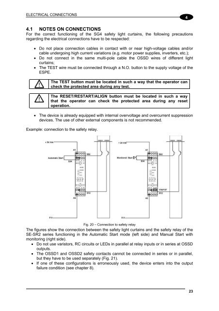
Example: connection to the safety relay.<br />
S12<br />
S52<br />
S52<br />
Fig. 20 – Connection to safety relay<br />
The figures show the connection between the safety light curtains and the safety relay of the<br />
SE-SR2 series functioning in the Automatic Start mode (left side) and Manual Start with<br />
monitoring (right side).<br />
Do not use varistors, RC circuits or LEDs in parallel at relay inputs or in series at OSSD<br />
outputs.<br />
The OSSD1 and OSSD2 safety contacts cannot be connected in series or in parallel,<br />
but they have to be used separately (Fig. 21).<br />
If one of these configurations is erroneously used, the device enters into the output<br />
failure condition (see chapter 8).<br />
23


