

SG4E Full Rev01.pdf - Datasensor
SG4E Full Rev01.pdf - Datasensor
SG4E Full Rev01.pdf - Datasensor

Create successful ePaper yourself
Turn your PDF publications into a flip-book with our unique Google optimized e-Paper software.
ALIGNMENT PROCEDURE<br />
5<br />
5 ALIGNMENT PROCEDURE<br />
The alignment between the emitting and the receiving units is necessary to obtain the correct<br />
functioning of the light curtain.<br />
A good alignment prevents output’s instability caused by dust or vibrations.<br />
The alignment is perfect if the optical axes of the first and the last emitting unit's beams<br />
coincide with the optical axes of the corresponding elements of the receiving unit.<br />
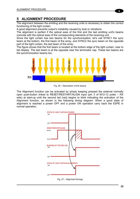
Since the light curtain has two beams for the synchronization, let’s call SYNC1 the sync<br />
beam at the bottom, the first beam of the array, and SYNC2 the sync beam on the opposite<br />
part of the light curtain, the last beam of the array.<br />
The figure shows that the first beam is located at the bottom edge of the light curtain, near to<br />
led display. The last beam is at the opposite near the terminator cap. These two beams are<br />
the synchronization beams too.<br />
1st beam<br />
Nth beam<br />
last beam<br />
Fig. 26 – Description of the beams<br />
The Alignment function can be activated by simply keeping pressed the external normally<br />
open push-button linked to RESET/RESTART/ALIGN input (pin 3 of M12-12 poles – RX<br />
side) at start-up until the second led (red) begins to blink indicating the activation of the<br />
Alignment function, as shown in the following timing diagram. When a good state of<br />
alignment is reached a power OFF and a power ON operation carry back the ESPE in<br />
normal operation.<br />
STATE OF LIGHT CURTAIN (POWER)<br />
ON<br />
OFF<br />
RESET/RESTART/ALIGN<br />
24Vdc<br />
0Vdc<br />
BLINKING OF THE RED LED<br />
ON<br />
OFF<br />
STATE OF LIGHT CURTAIN (ALIGNMENT)<br />
ON<br />
OFF<br />
Fig. 27 – Alignment timings<br />
25


